Epson 4500 User Manual
Page 184
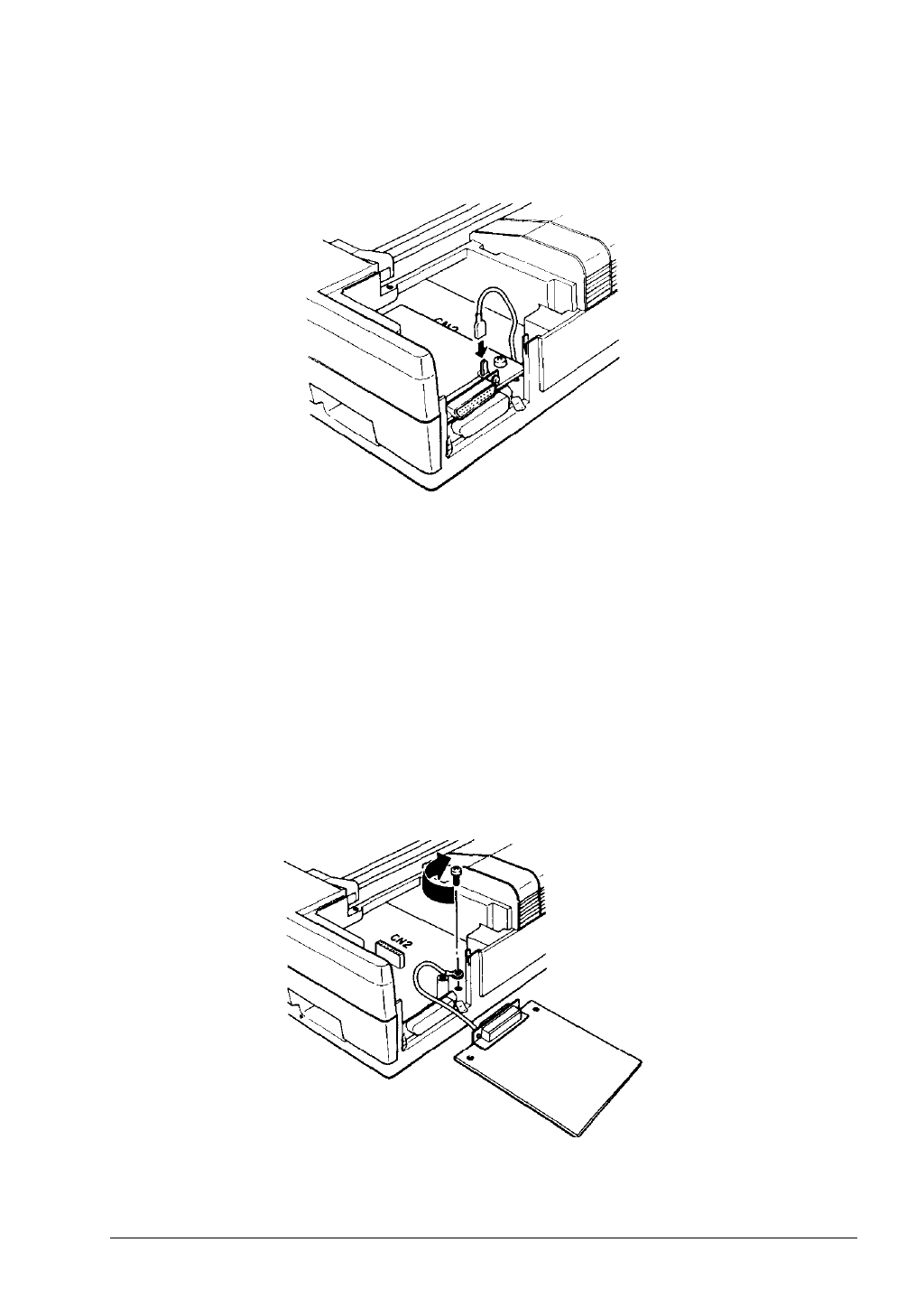
The Interface Boards
3. Attach the plug end of the FG wire onto the FG pin located on top
of the interface board.
4. Set the DIP switches on the interface board according to the manual
accompanying it.
FG wire attached
1. Carefully place the interface board next to the printer as shown
below. Use the CG screw to connect the round end of the FG
(frame ground) wire to the main board.
5-46
Using the Printer Options
See also other documents in the category Epson Printers:
- Stylus Pro 7800 (11 pages)
- Stylus Pro 4000 (49 pages)
- Stylus Photo R300 (2 pages)
- Stylus Pro 7000 (147 pages)
- AcuLaser C3000 (316 pages)
- Stylus Pro 7900 (24 pages)
- Stylus Pro 4450 (21 pages)
- 1000 (272 pages)
- T034120 (4 pages)
- T580300 (4 pages)
- 300 (91 pages)
- B 510DN (190 pages)
- B 510DN (218 pages)
- Stylus NX510 (8 pages)
- Stylus Photo RX580 (95 pages)
- T549300 (4 pages)
- B 500DN (168 pages)
- AculaserCX11NF (5 pages)
- 480SXU (24 pages)
- STYLUS RX500 (99 pages)
- 2100 (13 pages)
- Stylus NX215 (2 pages)
- T098320 (4 pages)
- T041020 (4 pages)
- R210 (8 pages)
- All-In-One Stylus Photo RX600 (164 pages)
- 777I (53 pages)
- T033120 (4 pages)
- Stylus CX7000F (8 pages)
- 60 (113 pages)
- T034220 (4 pages)
- WorkForce 40 Series (36 pages)
- T054220 (4 pages)
- Stylus CX3200 (11 pages)
- Stylus CX7800 (18 pages)
- T060220 (4 pages)
- 2500 (180 pages)
- AcuLaser CX11N (4 pages)
- AcuLaser CX11N (32 pages)
- 2000P (16 pages)
- T606600 (4 pages)
- Stylus CX6000 (18 pages)
- FS-4000DN (2 pages)
- MSDS T544700 (4 pages)