Operation 4. cleaning & maintenance – Sealey VS0205 User Manual
Page 2
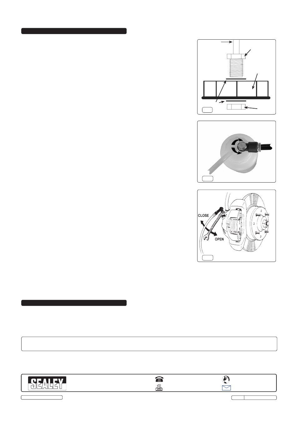
fig.3
3.1.
Brake bleeding procedure.
Refer to the vehicle manufacturer’s instructions for brake bleeding and wheel sequence
before proceeding. If no specific instructions from the vehicle manufacturer exist, follow
the instructions detailed below.
WARNING! Familiarise yourself with the hazards of brake fluid - read
manufacturer’s instructions on the container.
NOTE: Ensure that the brakes are adjusted before proceeding with bleeding the brakes.
3.1.1. For vehicles fitted with servo assisted brakes, pump the brake pedal two or three times
with the engine switched off to evacuate the air from the servo.
3.1.2. Remove the reservoir cap from the vehicles brake master cylinder, select and fit, see
fig.1, the appropriate adaptor cap to the automatic brake bleeder and connect to the
master cylinder.
3.1.3. Adjust the tyre pressure of one of the vehicles tyres or use a spare wheel to a maximum
of 20 psi and connect the automatic brake bleeder.
3.1.4. Pressure test the bottle with no brake fluid to ensure that the bottle has no leaks and
then release the pressure, disconnect from the tyre and fill the pressure bottle with new
clean brake fluid.
WARNING! DO NOT overtighten the pressure bottle cap. Check that the seal is correctly
seated in the cap before use and screw onto the pressure bottle until contact with the
seal is achieved, tighten no more than 1/8th of a turn after this contact point.
3.1.5. Ensure that the regulator (fig.2) on the top of the bottle is in the closed position connect
the air line to the tyre. Ensure that the pressure bottle is in a safe upright position.
3.1.6. Slowly open the regulator anti-clockwise to pressurise the brake system, checking to
ensure there are no leaks.
NOTE: The 20 psi quoted is as a guide only, pressures as low as 10 psi can successfully bleed
the brakes, adjust the regulator valve accordingly to the vehicle being worked on.
3.1.7. Starting from the bleed nipple furthest away from the master cylinder, attach a bleed tube
and place the other end into a suitable container. Loosen the bleed nipple (fig.3) to allow
the old brake fluid to flow into the container, when the fluid is clean and free from air
re-tighten the nipple.
3.1.8. Repeat the operation for the remaining bleed nipples in the sequence recommended by
the manufacturer.
NOTE: Ensure that the pressure bottle does not run out of brake fluid, if topping up is required,
close the regulator and disconnect from the tyre, before replenishing the brake fluid.
3.1.9. When the bleeding operation is complete, disconnect from the tyre
BEFORE removing
from the brake master cylinder.
3.1.10. If required top up the brake fluid in the reservoir to the maximum level and replace the
original reservoir cap.
3.1.11. Re-pressurise the tyre to its normal operating pressure.
NOTE: When brake bleeding and/or fluid changing is complete, test the action of the brake
pedal to ensure that the brakes are working and are not spongy before using the vehicle
on the road.
3.2.
Tandem Master Cylinder Brake Systems.
3.2.1. Some vehicles require two lines to be bled simultaneously (normally one front and one
rear), in this situation open both bleed nipples and control the flow using the regulator on
the top of the pressure bottle.
3.3.
Uncommon Brake Systems.
3.3.1. In some cases the master cylinder outlet is below the inlet, this may require pumping the
pedal once or twice in conjunction with the pressure bleed to remove any trapped
pockets of air. Alternatively the vehicle can be jacked up to raise the outlet.
3.4.
Clutch bleeding procedure.
Refer to the relevant vehicle manufacturer’s instructions for clutch bleeding procedure. If
no specific instructions from the vehicle manufacturer exist, the same procedures as for
brake bleeding should be followed.
3. OPERATION
4. CLEANING & MAINTENANCE
4.1.
Ensure that the unit is depressurised before carrying out any maintenance and drain all fluids from the pressure bottle and tubes.
Clean up any spilt brake fluid and wipe down with a clean cloth. Store in a clean, dry and childproof location.
01284 757500
01284 703534
www.sealey.co.uk
Web
NOTE:
It is our policy to continually improve products and as such we reserve the right to alter data, specifications and component parts without prior notice.
IMPORTANT: No liability is accepted for incorrect use of this product.
WARRANTY: Guarantee is 12 months from purchase date, proof of which will be required for any claim.
INFORMATION: For a copy of our catalogue and latest promotions call us on 01284 757525 and leave your full name, address and postcode.
fig.1
Lock Nut
Brass Fitting
Adaptor Cap
& Seal
Fibre Washers
Supply Pipe
fig.2
OFF
ON
Parts support is available for this product. To obtain a parts list and diagram please log on to www.sealey.co.uk, email sales@sealey.
co.uk or phone 01284 757500
Sole UK Distributor, Sealey Group,
Kempson Way, Suffolk Business Park
,
Bury St. Edmunds, Suffolk,
IP32 7AR
Original Language Version
© Jack Sealey Limited
VS0205 Issue: 2(L) - 02/12/13