Fig.14, Fig.15 – Sealey PP100 User Manual
Page 5
Original Language Version
PP100 issue: 2 - 06/03/12
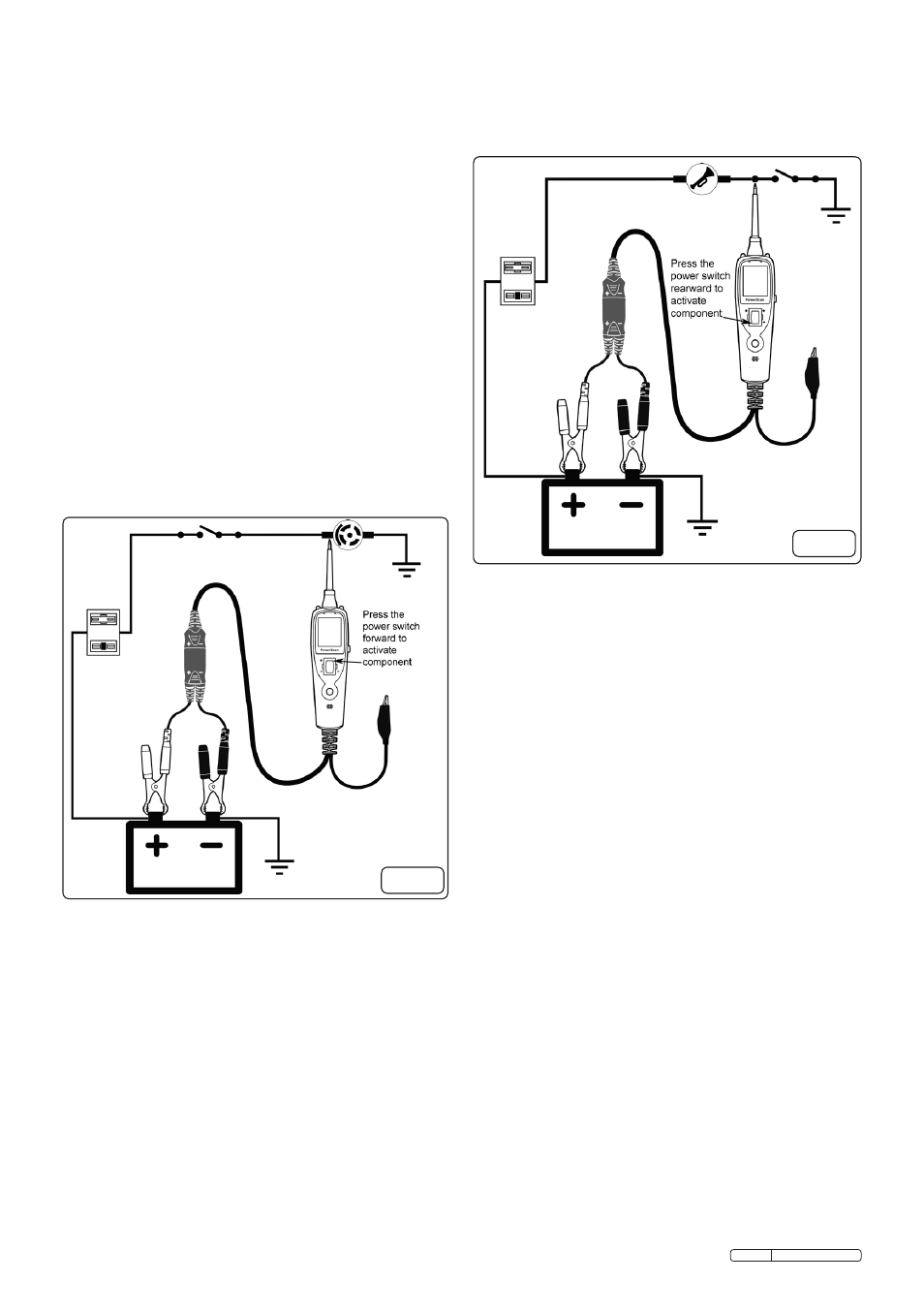
4.6 activating components with a positive (+)
voltage within vehicle electrical system
4.6.1 set up the tool as shown in fig.14 and set to
voltage mode.
4.6.2 contact the probe tip to the positive terminal of
the component, the test indicator should
illuminate green. Whilst observing the test
indicator, quickly press and release the power
switch forward to the positive position. if the
indicator changes instantly from green to red the
tool is ready for use.
4.6.3 if the circuit breaker activates, the unit has
been overloaded. this could happen for the
following reasons:
a) the tip’s contact went to direct earth.
b) the component has a short circuit.
c) the component is a high current component
(i.e. starter motor)
warninG! randomly applying voltage to
certain circuits can cause damage to a
vehicle’s electronic components. it is strongly
advised to use the correct circuit diagram and
diagnostic procedures whilst performing this
test.
fig.14
4.7 activating components with a negative (-)
voltage within vehicle electrical system
4.7.1 set up the tool as shown in fig.15 and set to
voltage mode.
4.7.2 contact the probe tip to the negative terminal of the
component, the test indicator should illuminate red.
Whilst observing the test indicator, quickly press the
power switch rearwards to the negative position
and release it. if the indicator changes instantly
from red to green the tool is ready for use.
4.7.3 if the circuit breaker activates, the unit has been
overloaded. this could happen for the following
reasons:
a) Where the tip of the tester has contacted is a
direct positive voltage.
b) the component has a short circuit.
c) the component is a high current component
(e.g. a starter motor).
fig.15
warninG! with this function a vehicle’s fuses
may blow when the probe tip is earthed in
series with them.
4.8 checking for bad earth contacts
4.8.1 With the tool connected to the battery supply, set
to the voltage mode.
4.8.2 Probe the suspected earth wire or contact with the
probe tip. observe the colour of the test indicator.
4.8.3 Press the power switch forward to the positive
position and release it. if the test indicator
changes from green to red, this is not a true earth.
4.8.4 if the circuit breaker tripped when the power
switch was pressed forward, this circuit is
more than likely a direct earth. note that high
current components such as a starter motor will
also cause the test indicator to trip off during this
check.
4.9 following and Locating short circuits
4.9.1 in most cases a short circuit will appear by a fuse
or a fusible link blowing or an electrical protection
device tripping (i.e. a circuit breaker).
this is the best place to begin the search.
4.9.2 connect the tool to the battery supply. remove
the blown fuse from the fuse box. use the probe
to activate and energise each of the fuse
contacts. the contact which trips the probe
circuit breaker is the shorted circuit. take note of
this wire’s identification code or colour.
4.9.3 follow the wire as far as you can along the wiring
harness. for instance if you are following a short
in the brake light circuit you may know that the
wire must pass through the wiring harness at the
door sill. Locate the colour-coded wire in the
harness and expose it.