Fig.11, Fig.12, Fig.13 – Sealey PP100 User Manual
Page 4
Original Language Version
PP100 issue: 2 - 06/03/12
4.3 signal circuit testing
4.3.1
the tool can be used as a trouble shooting aid to
test sensors/components in a circuit where a Dtc
(Diagnostic trouble code) has been detected
during an on-board diagnostic scan.
4.3.2 Always refer to the vehicle manufacturer’s service
instructions, or a proprietary manual to establish
the current procedure and data for testing and
location of the sensor/component to be tested.
4.3.3 set the tool to scope mode and attach the
auxiliary ground lead to earth.
use the probe tip
on the terminals of the sensor/component as
described in the manufactuer’s test procedures
and observe the signal and readings on the LcD
display screen (fig.11).
4.3.4 Any abnormal signals or readings may indicate a
fault with the sensor/component.
fig.11
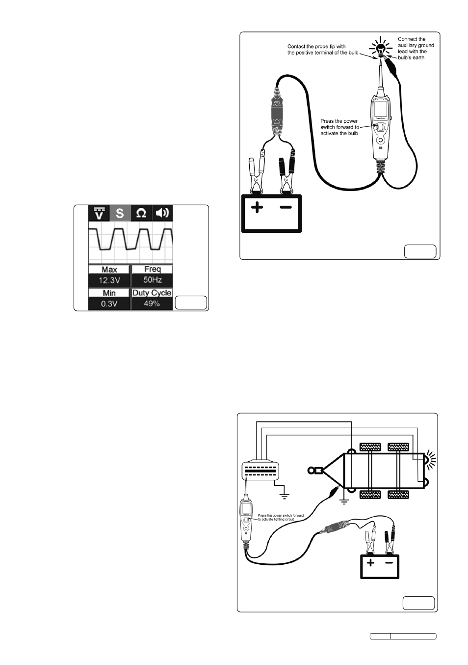
4.4 activating components removed from
vehicle electrical system (such as fuel
pumps, starter solenoids, magnetic clutches,
blower motors, cooling fans, lights etc.)
4.4.1 By using the probe tip together with the auxiliary
earth lead, components can be activated, thereby
testing their function.
4.4.2 set the tool to the voltage mode.
4.4.3 connect the auxiliary earth lead’s clip to the
negative terminal of the component to be tested.
contact the probe to the positive terminal of the
component. the test indicator should illuminate
green, indicating continuity through the
component (fig.12).
4.4.4 Quickly press the power switch forward to the
positive position and release. if the test
indicator changes from green to red, you may
proceed with further activation. Press and hold
the power switch forward to energise the
component being tested.
4.4.5 if circuit breaker activates, the unit has been
overloaded. this could happen for the following
reasons:
a) Where the tip of the tester has made contact is
a direct earth or a negative voltage.
b) the component has a short circuit.
c) the component requires a high current (e.g. a
starter motor).
note: the tool is equipped with a built in circuit
breaker for overload protection. should the circuit
breaker be activated, reset using the circuit
breaker reset (fig.1 item5).
fig.12
4.5 testing trailer Lights and connections
4.5.1 set the tool to the voltage mode.
4.5.2 connect to a battery of the correct voltage for the
trailer electrical system (fig.13).
4.5.3 clip the auxiliary earth lead to an earth on the
trailer chassis.
4.5.4 Probe the contacts of the trailer’s electrical
connection socket whilst pressing the power
switch forward to the positive position. this
will allow you to check the function and
orientation of the trailer lighting system.
fig.13