Ella Moss Automobile Parts User Manual
Page 33
M:\Product Information\366-348\Instructions\366-348 MGB Fuel Injection Installation Instructions_Grant_2.doc
Part 18, continued
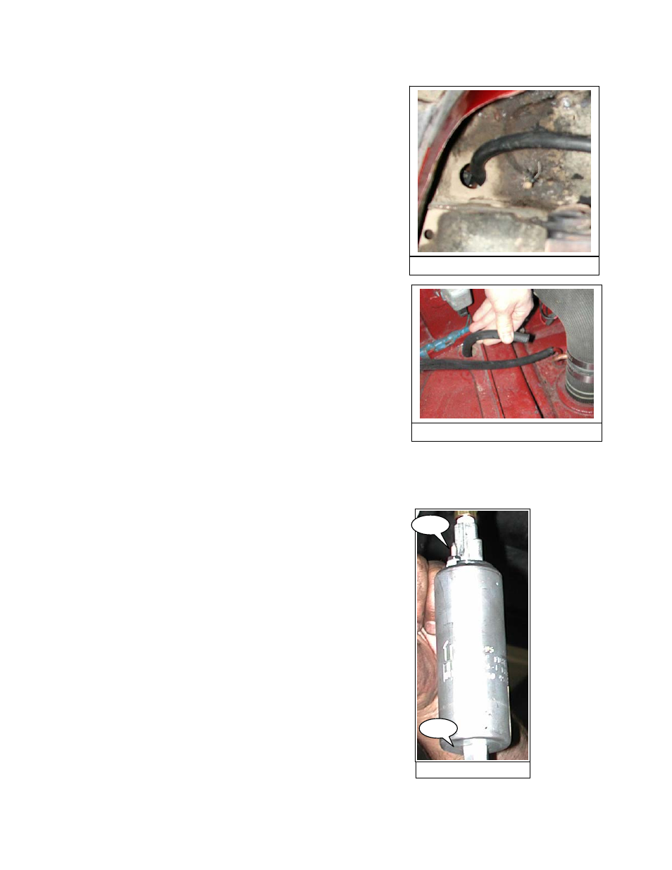
366-348 Inst Fig 138
217.
Replace the plastic plug/grommet in the hole in the
trunk floor and push the hose through the hole in the
plug and into the trunk. (Fig 138)
218.
From inside the trunk, pull the hose until you have
taken up most of the slack. (figure 139)
366-348 Inst Fig 139
219.
Go back over the route of the hose, adjusting it as
needed to relieve stress and to route the hose around
sharp edges or other hazards. Zip-tie the hose to the
hard lines and/or other hoses where appropriate. From
inside the trunk, pull in any remaining slack if necessary.
This is as much as we can do with this hose at this time.
This completes part 18 of the installation
Installation Part 19 – Connecting the High Pressure Fuel Pump
220.
Find the following:
366-348 Inst Fig 165
165.1
165.2
one high pressure pump
four small hose clamps
a 36 inch length of 5/16” fuel hose
a 24 inch length of 5/16” fuel hose
All of these are in the kit.
221.
Examine the pump. One end (165.1) has electrical
connectors. The other end (165.2) does not. The hose
fittings have already been installed, and you will see
Teflon tape on the threads of the fittings. For the next
several steps, we will be working with the fuel pump
suspended or hanging underneath the car because we
have found that once mounted, it is very hard to get to
the pump.
Page 33 of 52