Ella Moss Automobile Parts User Manual
Page 11
M:\Product Information\366-348\Instructions\366-348 MGB Fuel Injection Installation Instructions_Grant_2.doc
58. Hang the modified heat shield assembly in position, (with
the gasket toward the manifold) using the stud on the
water pipe to support the heat shield. The four bolt holes
in the heat shield should line up with the four holes in the
manifold. Replace the nut on the stud on the water pipe
loosely- we just want to keep the heat shield assembly in
position.
366-348 Inst Fig 20
20.1
59. Apply a drop or two of blue Loctite to the threads of the
two lower bolts. The Loctite in the kit is in s small plastic
tube. Cut of a corner to make a very small opening and
squeeze a little Loctite on the threads. You only need a
drop of two.
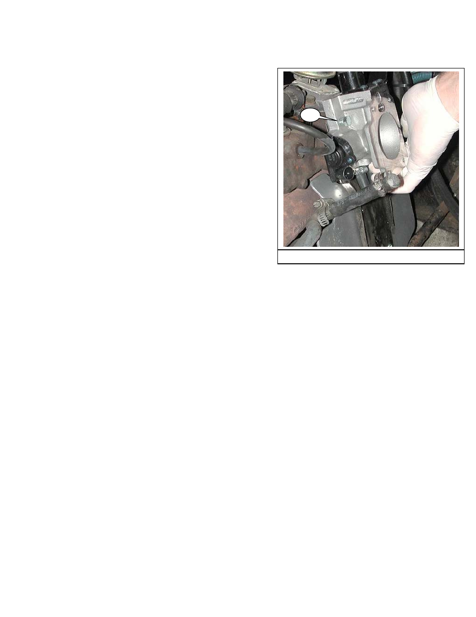
60. Hold the throttle body with the throttle bell crank toward
the rear of the car. Carefully position the throttle body in
the engine compartment. You will have to hold the two
lower bolts in place as you maneuver the assembly into
position. (Fig 20)
61. Hold the throttle body up against the heat shield and
thread the two lower bolts through the heat shield and
into the threaded holes in the manifold, starting with the
lower front bolt (the one on your left as you look at the
throttle body).
62. Apply a drop or two of blue Loctite to the threads of the
two upper bolts (5/16-18 X 1”). Thread them into place
starting with the upper left bolt (20.1).
63. Once all four bolts are started, tighten them using a ½”
open end wrench. They should be torqued to 18 ft-lbs.
There is no way to get a torque wrench in there,
although you might get a crows-foot on a bolt. If you are
not comfortable judging 18 ft-lbs, tighten a bolt you can
get to 18 ft-lbs, then put a wrench on it to see what 18 ft-
lbs feels like. This completes part 4 of the installation.
Page 11 of 52