Ella Moss Automobile Parts User Manual
Page 15
M:\Product Information\366-348\Instructions\366-348 MGB Fuel Injection Installation Instructions_Grant_2.doc
Installation Part 7 – Installing the Manifold Absolute Pressure (MAP) Sensor
The MAP sensor is a variable resistor used to monitor the
difference between the pressure inside the intake manifold
and normal atmospheric pressure outside the manifold.
This information is used by the electronic Control Unit
(ECU) to determine engine load. When the engine is under
load, the computer will alter the fuel mixture to improve
performance and reduce emissions. Before we get started
we need to make a place for the MAP sensor. Some late
MGBs came equipped with a mechanical fuel cut-off valve
that sits on the firewall shelf near the pedal box and fuel
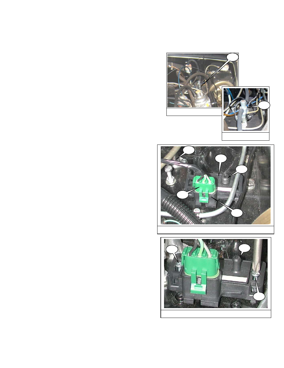
filter. The valve (27.1, 27.2) is connected to the fuel hose
between the fuel filter and the carb. These valves are
prone to failure, and most of them have already been
removed. If you have one, we suggest thay you remove it
366-348 Inst Fig 27B
27.2
366-348 Inst Fig 27A
27.1
along with the 2 pieces of hose attached to the valve.
77. Locate separate bag that contians the Manifold
Absolute Pressure (MAP) sensor. It is a small black
plastic box (27.3) with a nipple for a vacuum hose
(27.4) and a socket for a wiring connector (27.5).
366-348 Inst Fig 27C
27.3
27.5
27.4
27.7
27.6
78. Connect the harness plug (27.6) and position the MAP
sensor so there is slack in the wires. It fits nicely on
the firewall shelf near where the throttle cable guide is
mounted (27.7).
79. There are two slots for screws at either end of the
plastic box; the screws can be positioned anywhere in
those slots. Mark the position of one of the screws.
80. Remove the MAP sensor and look under the dash in
the cockpit- make sure there are no wires in the area-
you are about to drill a couple of holes.
81. Center punch your mark and drill one hole using a
3/32” drill bit.
366-348 Inst Fig 28
28.1
28.3
28.2
82. Find the two #6 x 1 ¼” sheet metal screws and the two
#6 flat washers provided in the kit. Secure the MAP
sensor to the firewall shelf using one screw and
washer (28.1).
83. Using the MAP sensor as a guide, drill a second hole
using a 3/32” drill bit and install the second screw and
flat washer. (28.1) Do not over-tighten. The flat
washers were not used in the installation
photographed- that’s when we decided they were
needed.
84. Pull the rubber bellows/cover (see 27.2 on previous
page) off the vacuum nipple, exposing the plastic hose
barb (28.3).
This completes part 7 of the installation.
Page 15 of 52