Rear panel features, Chapter 1, Introduction – Lanner LEC-7100 User Manual
Page 7
4
Introduction
Chapter 1
Embedded and Industrial Computing
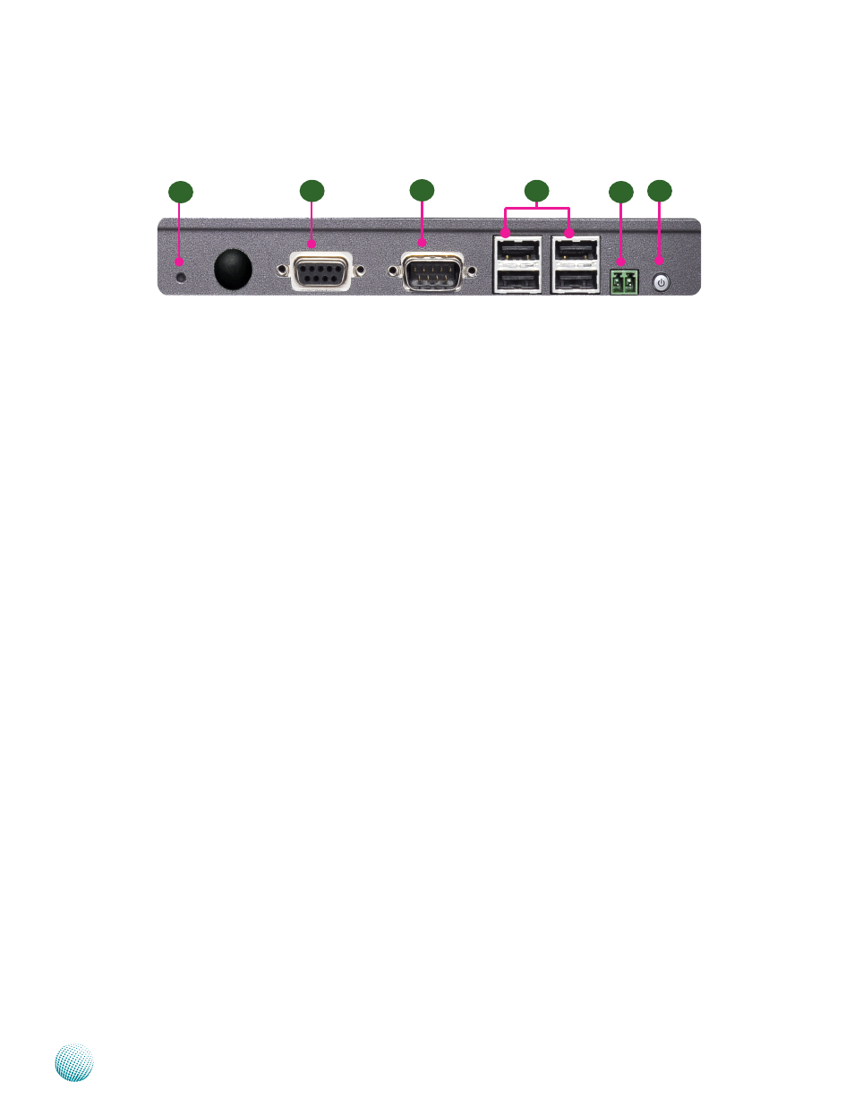
Rear Panel Features
R1
R2
R5
R6
R3
F4
R1 Reset Switch
It is a hardware reset switch. Use this switch to reset the system without
turning off the power.
R2 DIO Port (DB-9 female connector)
The general-purpose input/output (GPIO) peripheral provides dedicated
general-purpose pins to support connection of digital I/O devices.
R3 RS-232 COM Port (DB-9 Male Connector)
Using suitable RS-232 cable, you can connect an appropriate device, for
example, a terminal console for diagnostics. This port is assigned as COM1.
The default configuration parameter: 9600 baud rate, 8 data bits, no parity,
1stop bit, and no flow control.
R4 Four USB 2.0 Ports
It connects to any USB devices such as a flash drive. The left-bottom one is
defined as USB0 whereas the left-upper one is USB1; the right-bottom one
is defined as USB2 whereas the right-upper one is USB3.
R5 Power Switch through Phoenix Contact
It is a power-on switch. You could turn on or off the system power by using
this contact in stead of the following power switch.
R6 Power-on Switch
If the LED is green, it indicates that the system is powered on; if the LED is
red, it indicates that the system is in Standby mode.