Jumper settings, Chapter 3, Motherboard information – Lanner LEC-7100 User Manual
Page 12
9
Motherboard Information
Chapter 3
Embedded and Industrial Computing
Jumper Settings
M1
Power/Hard Disk LED (LED1): The power and hard disk
LED indicator.
M2
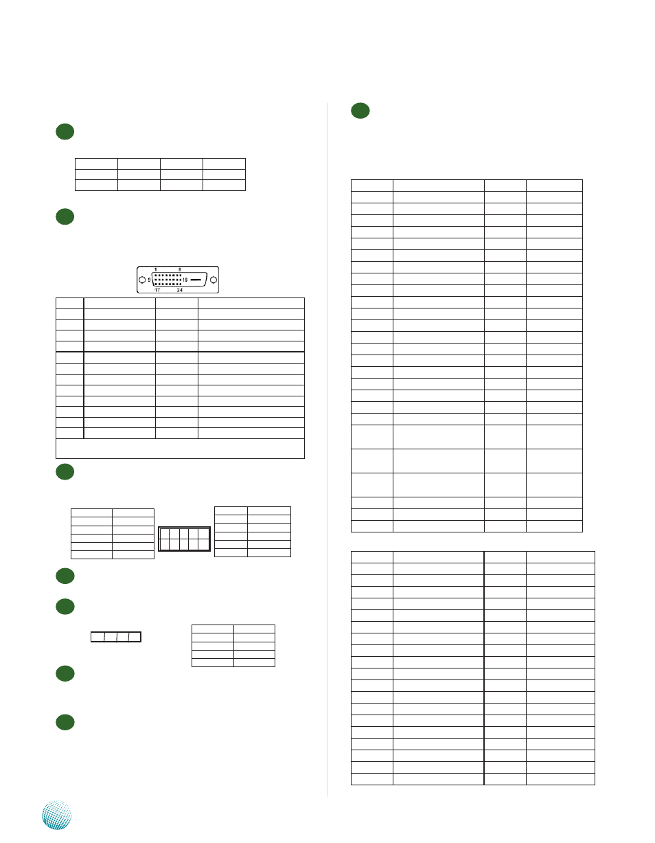
DVI-D Connector(CN3): The DVI (Digital Visual
Interface) is a standard for high resolution digital
displays. Below is a 24-Pin DVI Female connector ‘s
pinout.
M3
SPI-ROM(J1): Using the appropriate cable to connect
this 10-pin ISP in header connector, the user can
update the SPI Flash soldered on board
M4
Serial-ATA Connector (J4/J5): It is for connecting a 2.5''
SATA harddisk to be served as your system's storage.
M5
4-pin Serial-ATA Power Connector (J3): It is for
connectig the SATA power cord.
M6
SIM Socket (CN9): It is for connecting SIM card of the
mobile connection.
M7
Compact Flash Connector (CN11): It is for connecting
a Compact Flash card to be served as your system's
storage.
Pin No.
Function
Pin No.
Function
C2
HDD LED N
A2
HDD LED P
C1
PWD LED N
A1
PWR LED P
2 4 6 8 1 0
1 3 5 7 9
Pin No.
Function
2
RSVD
4
+3.3V
6
RSVD
8
SPI_CLK
10
SPI_MOSI
Pin No.
Function
1
SPI_HOLD_N
3
SPI_CS0_N
5
SPI_MISO
7
RSVD
9
GND
4 3 2 1
Pin No.
Function
1
5V
2
Ground
3
Ground
4
12V
Pin No.
Function
Pin No.
Function
1
TMDS Data2-
13
Reserved
2
TMDS Data2+
14
+5V Power
3
Ground
15
Ground (for+5V)
4
Reserved
16
Hot Plug Detect
5
Reserved
17
TMDS Data()-
6
Reserved
18
TMDS Data()+
7
Reserved
19
Ground
8
Reserved
20
Reserved
9
TMDS Data1-
21
Reserved
10
TMDS Data 1+
22
TMDS Clock Shield
11
Ground
23
TMDS Clock +
12
Reserved
24
TMDS Clock -
Note that some pins are assigned as Reserved which is different from the
standard DVI-D pinout.
M8
Mini-PCIe Socket(CN10/CN12): It is for connecting
any Mini-PCIe adapter such as a Wi-Fi module (CN10)
or connecting Wireless 3G module (CN12) for mobile
Internet connections.
CN10 Pin Assignment
PIN NO. Description
PIN NO. Description
1
WAKE#
2
3.3V
3
Reserved
4
GND
5
Reserved
6
1.5V
7
CLKREQ#
8
UIM_PWR
9
GND
10
UIM_DATA
11
REFCLK-
12
UIM_CLK
13
REFCLK+
14
UIM_RESET
15
GND
16
UIM_VPP
17
Reserved (UIM_C8) 18
GND
19
Reserved (UIM_C4) 20
ENABLE
21
GND
22
PERST#
23
PERn0
24
+3.3Vaux
25
PERp0
26
GND
27
GND
28
+1.5V
29
GND
30
SMB_CLK
31
PETn0
32
SMB_DATA
33
PETp0
34
GND
35
GND
36
USB_D-
37
Reserved
38
USB_D+
39
Reserved
40
GND
41
Reserved
42
LED_
WWAN#
43
Reserved
44
LED_
WLAN#
45
Reserved
46
LED_
WPAN#
47
Reserved
48
+1.5V
49
Reserved
50
GND
51
Reserved
52
+3.3V
CN12 Pin Assignment
PIN NO. Description
PIN NO. Description
1
WAKE#
2
3.3V
3
Reserved
4
GND
5
Reserved
6
1.5V
7
CLKREQ#
8
Reserved
9
GND
10
Reserved
11
REFCLK-
12
Reserved
13
REFCLK+
14
Reserved
15
GND
16
Reserved
17
Reserved (UIM_C8) 18
GND
19
Reserved (UIM_C4) 20
ENABLE
21
GND
22
PERST#
23
PERn0
24
+3.3Vaux
25
PERp0
26
GND
27
GND
28
+1.5V
29
GND
30
SMB_CLK
31
PETn0
32
SMB_DATA
33
PETp0
34
GND
35
GND
36
USB_D-
37
Reserved
38
USB_D+