Front panel features, Chapter 1, Introduction – Lanner FW-7610 User Manual
Page 6
3
Introduction
Chapter 1
Network Application Platforms
L A N 1 L A N 2 L A N 3 L A N 4 L A N 5 L A N 6 L A N 7 L A N 8
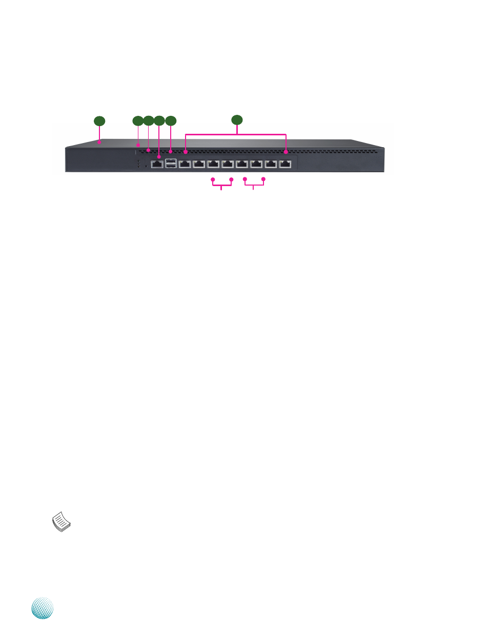
Front Panel Features
F1 System Panel: LCD System Panel (for customization only)
The LCD System Panel can be programmed to display operating status and configuration information. For more details or
sample programming code, please refer to the Appendix C.
F2 Power/Status/HDD LED
Power: If the LED is on it indicates that the system is powered on. If it is off, it indicates that the system is powered off.
Status: If the LED is green, it indicates that the system’s operational state is normal. If it is red, it indicates that the system is
malfunctioning.
HDD: If the LED is on, it indicates that the system’s storage is functional. If the LED blinks, it indicates data access activities.
If it is off, it indicates that there is no hard disk present or functional.
F3 Reset Switch
The reset switch can be used to reboot the system without turning off the power.
F4 Console Port
By using suitable rollover cable or RJ-45 to DB-9 Female (Cisco console cable), you can connect to a computer terminal for
diagnostic or configuration purpose. The default terminal Configuration Parameters: 115200 baud, 8 data bits, no parity, 1
stop bit , no flow control.
F5 Two USB 2.0 Ports
It connects to any USB devices, for example, a flash drive. The system also supports two additional USB 2.0 ports with internal
pin headers.
F6 8 Gigabit LAN ports (provided by Intel 82574L GbE Controller)
Right LED (Speed):If the LED is orange, it indicates that the connection speed is 1000Mbps. If the LED is green, it indicates
that the connection speed is 100Mbps. And if it is off, it indicates that the speed is 10Mbps.
Left LED (Link/ACT): If the LED is on, it indicates that the port is active. If it blinks,
it indicates there is traffic.
LAN1 and LAN2 ports support PXE remote boot (note that you need to enable this in the BIOS menu). Moreover, 2 pairs (LAN3-
LAN4, LAN5-LAN6) can be configured as LAN Bypass when failure events occur. This feature can implemented dynamically
with a watch dog timer. Refer to Appendix E and your Driver and Manual CD for a sample implementation of this feature.
Note:
The availability of LAN Bypass varies depending on the model.
1.
The number of LAN ports varies depending on the model.
2.
F2
F1
F3
F4
F5
F6
LAN1 LAN2 LAN3 LAN4 LAN5 LAN6 LAN7 LAN8
Bypass Pair Bypass Pair