Chapter 3, Motherboard information – Lanner FW-7610 User Manual
Page 14
11
Motherboard Information
Chapter 3
Network Application Platforms
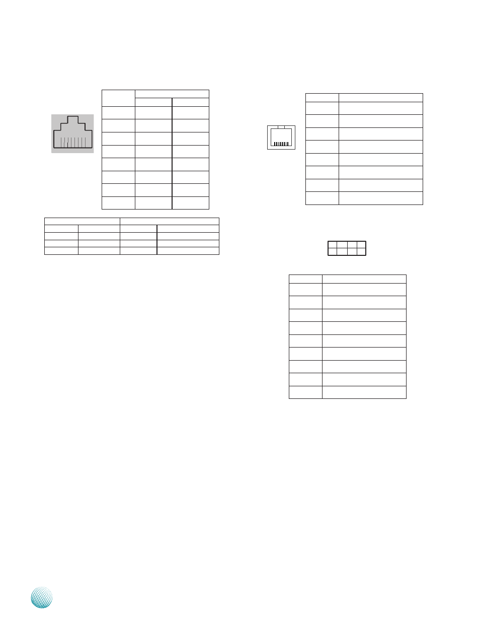
Ethernet ports (LAN1~LAN8)
LED1
LED2
Status
Description
Status
Description
Off
No Link
Off
10 Mbps Connection
On
Linked
Green
100 Mbps Connection
Blinking
Data Activity
Amber
1 Gbps Connection
Ethernet 1-8 Port : These RJ45 gigabit Ethernet ports are
provided by Intel 82574L GbE controller. Note you
need to enable this function in the BIOS menu.Only
LAN1 and LAN2 support PXE remote boot; Refer to
Chapter 1 Introduction and Chapter 4 BIOS settings
for more information.
PIN NO.
Function
Fast E-Net
Giga Net
1
TX+
BI_DA+
2
TX-
BI_DA-
3
RX+
BI_DB+
4
--
BI_DC+
5
--
BI_DC-
6
RX-
BI_DB-
7
--
BI_DD+
8
--
BI_DD-
Serial Port Connector (Console1): The Console port on
the front panel.
Serial Port Interface (COM1):
8 1
PIN NO.
Function
1
Request To Send (RTS)
2
Data Terminal Ready (DTR)
3
Transmitted Data (TxD)
4
Signal Ground
5
Signal Ground
6
Received Data (RxD)
7
Data Set Ready (DSR)
8
Clear To Send (CTS)
LED1
LED2
1 3 5 7 9
2 4 6 8 10
PIN NO.
Function
1
Data Carrier Detect (DCD)
2
Data Set Ready (DSR)
3
Received Data (RxD)
4
Request To Send (RTS)
5
Transmitted Data (TxD)
6
Clear To Send (CTS)
7
Data Terminal Ready (DTR)
8
Ring Indicator (RI)
9
Signal Ground