Parameters a - 9, Carrier freq, Preset reference (speeds) – Yaskawa P7 Drive User Manual User Manual
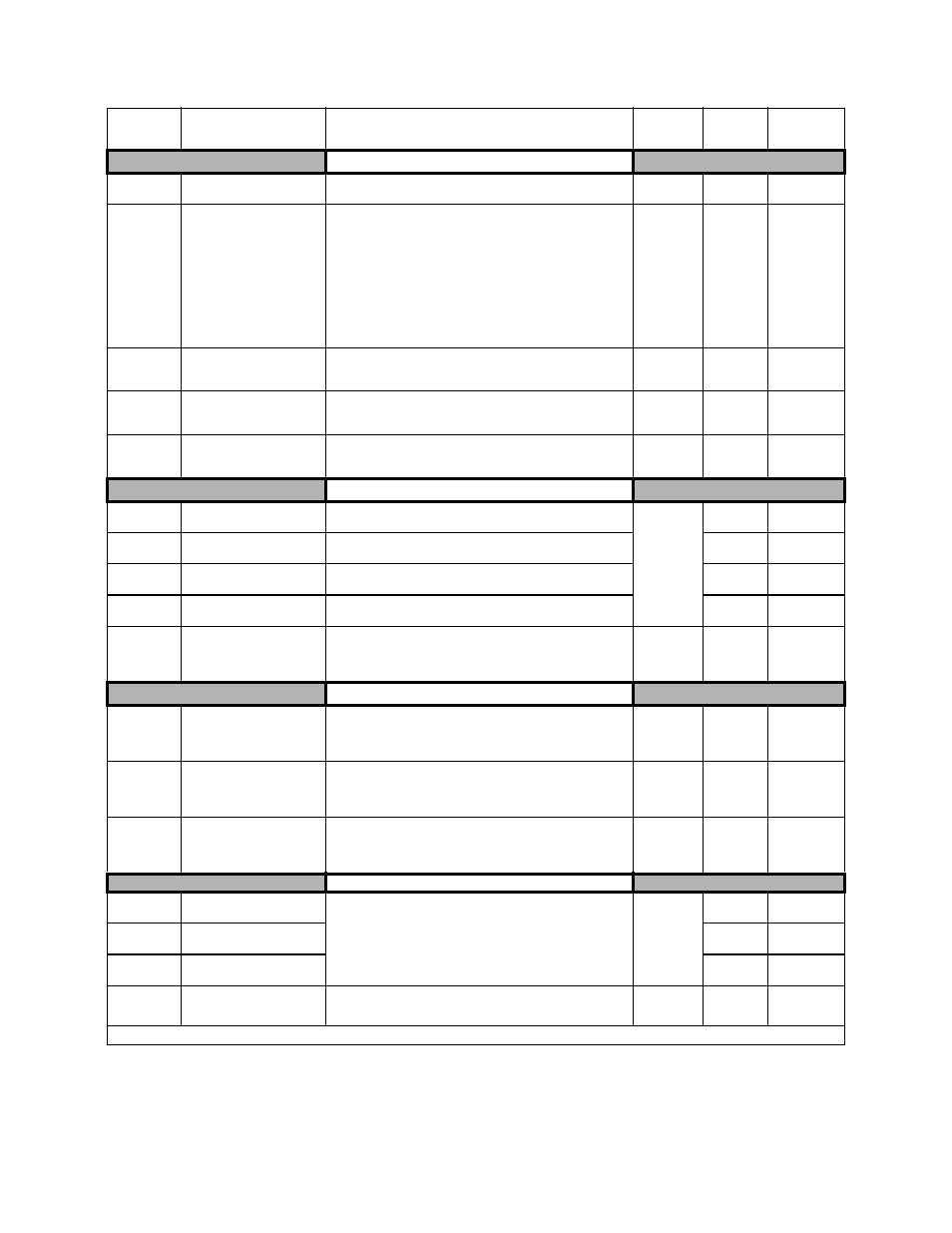
Page 183: Reference limits, Jump frequencies, Table 1: parameter list (continued)
Parameters A - 9
Carrier Freq
C6-01
Normal Duty Selection
Normal Duty Sel
1: Normal Duty 1
2: Normal Duty 2
1 or 2
2
Programming
C6-02
Carrier Frequency Selection
CarrierFreq Sel
Carrier frequency sets the number of pulses per second of the out-
put voltage waveform.
0: Low Noise (Carrier frequency is randomly moduled for lower
audible noise)
1: Fc = 2.0 kHz
2: Fc = 5.0 kHz
3: Fc = 8.0 kHz
4: Fc = 10.0 kHz
5: Fc = 12.5 kHz
6: Fc = 15.0 kHz
F: Program (Determined by the settings of C6-03 thru C6-05)
0 to F
kVA
Dependent
Programming
C6-03
Carrier Frequency Upper
Limit
CarrierFreq Max
Maximum carrier frequency allowed when C6-02 = F.
kVA
Dependent
kVA
Dependent
Programming
C6-04
Carrier Frequency Lower
Limit
CarrierFreq Min
Minimum carrier frequency allowed when C6-02 = F.
kVA
Dependent
kVA
Dependent
Programming
C6-05
Carrier Frequency Propor-
tional Gain
CarrierFreq Gain
Sets the relationship of output frequency to carrier frequency when
C6-02 = F.
0 to 99
0
Programming
Preset Reference (Speeds)
d1-01
Frequency Reference 1
Reference 1
Digital preset speed command 1. Used when b1-01 = 0. Setting
units are affected by o1-03.
0.00 to
E1-04
Value
0.00Hz
Programming
d1-02
Frequency Reference 2
Reference 2
Digital preset speed command 2. Selected via multi-function input
terminals. Setting units are affected by o1-03.
0.00Hz
Programming
d1-03
Frequency Reference 3
Reference 3
Digital preset speed command 3. Selected via multi-function input
terminals. Setting units are affected by o1-03.
0.00Hz
Programming
d1-04
Frequency Reference 4
Reference 4
Digital preset speed command 4. Selected via multi-function input
terminals. Setting units are affected by o1-03.
0.00Hz
Programming
d1-17
Jog Frequency Reference
Jog Reference
Speed command used when a jog is selected via multi-function
input terminals. Setting units are affected by o1-03.
0.00 to
E1-04
Value
6.00Hz
Programming
Reference Limits
d2-01
Frequency Reference Upper
Limit
Ref Upper Limit
Determines maximum speed command, set as a percentage of
parameter E1-04. If speed command is above this value, actual
drive speed will be limited to this value. This parameter applies to
all speed command sources.
0.0 to 110.0
100.0%
Quick Setting
d2-02
Frequency Reference Lower
Limit
Ref Lower Limit
Determines minimum speed command, set as a percentage of
parameter E1-04. If speed command is below this value, actual
drive speed will be set to this value. This parameter applies to all
speed command sources.
0.0 to 110.0
0.0%
Quick Setting
d2-03
Master Speed Reference
Lower Limit
Ref1 Lower Limit
Determines the minimum speed command, set as a percentage of
parameter E1-04. If speed command is below this value, actual
drive speed will be set to this value. This parameter only applies to
analog inputs A1 and A2.
0.0 to 110.0
0.0%
Programming
Jump Frequencies
d3-01
Jump Frequency 1
Jump Freq 1
These parameters allow programming of up to three prohibited
frequency points for eliminating problems with resonant vibration
of the motor / machine. This feature does not actually eliminate the
selected frequency values, but will accelerate and decelerate the
motor through the prohibited bandwidth.
0.0 to 200.0
0.0Hz
Programming
d3-02
Jump Frequency 2
Jump Freq 2
0.0Hz
Programming
d3-03
Jump Frequency 3
Jump Freq 3
0.0Hz
Programming
d3-04
Jump Frequency Width
Jump Bandwidth
This parameter determines the width of the deadband around each
selected prohibited frequency point. A setting of “1.0” will result in
a deadband of +/- 1.0 Hz.
0.0 to 20.0
1.0Hz
Programming
Denotes that parameter can be changed when the drive is running.
Table 1: Parameter List (Continued)
Parameter
No.
Parameter Name
Digital Operator Display
Description
Setting
Range
Factory
Setting
Menu
Location