Z1000u bypass quick start procedure, 7 route signal wiring, Page 15 of 37 – Yaskawa Z1000U HVAC Matrix Bypass User Manual
Page 15
YASKAWA TOEP YAIZ1D01A Z1000U Matrix Bypass Quick Start Procedure
Z1000U Bypass
Quick Start Procedure
Page 15
of 37
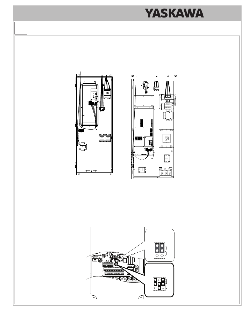
7.7 Route signal wiring.
Properly route signal wiring to reduce coupling of external noise to signal wiring. Attempt to route and secure signal wiring at least one
inch away from power wiring for parallel routing. Route control wiring a right angles when crossing power wiring and control wires within
the drive enclosure.
C
B
E(G) IG R+ R- S+ S-
S1 S2 S3 S4 S5 S6 S7 S8 SN SC SP
V+ AC A1 A2 A3 FM AM AC
24V
RP AC
M1 M2 M3 M4
MD ME MF
MA MB MC
C
B
E(G) IG R+ R- S+ S-
S1 S2 S3 S4 S5 S6 S7 S8 SN SC SP
V+ AC A1 A2 A3 FM AM AC
24V
RP AC
M1 M2 M3 M4
MD ME MF
MA MB MC
A
Models D024 to D114 and B011 to B124
Models D143 to D211 and B156 to B414
A
A - Control, frequency reference, and
communications wiring
B - Motor output circuit
C – Main input circuit
7.8 Verify or set Jumper S1 on the drive to match the frequency reference signal type.
Confi rm Jumper S1 on the drive (A1,A2, Volt/Current Selection) is set to match the frequency reference signal type, either voltage
(V) or current (I) for Z1000U terminals TB3 - A1 and A2.
•
Factory default setting of TB3 - terminal A1 is 0 - 10 Vdc/100%.
•
Factory default setting of TB3 - terminal A2 is 4 - 20 mA/100%.
E(G) IG R+ R- S+ S-
S1 S2 S3 S4 S5 S6 S7 S8 SN SC SP
V+ AC A1 A2 A3 FM AM AC
24V
RP AC
M1 M2 M3 M4
MD ME MF
MA MB MC
Selection
Jumper S5
Terminal AM/FM Signal
Jumper S1
A1/A2/A3 Volt/Curr.
Selection
V
I
A1 A2 A3
V
AM
FM
I
Confi gure the HAND and AUTO Frequency Reference (continued)
7
STEP