Mechatrolink connection, Figure 5.8: terminal connectors, I/o350 – Yaskawa MP940 Hardware Manual User Manual
Page 31
MotionSuite™ MP940 Machine Controller Hardware Manual
Section 5: Communications
28
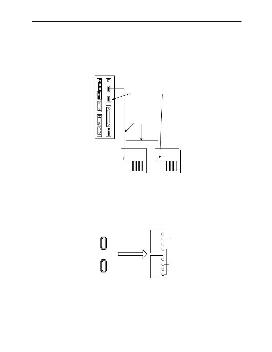
Mechatrolink Connection
The following figure shows the connection of the MP940 module to an I/O350 unit.
Use the standard cable (JEPMC-W6000-A3) when connecting an MP940 module to
an I/O350, or when connecting one I/O350 to another I/O350.
Insert the USB terminator (JEPMC-W6020) into the terminal connector ((1) or (2) in
the figure below). The mechatrolink connectors 1 and 2 are the same; the terminator
may be inserted into either one.
Insert a USB terminator (JEPMC-W6020) into unused ports.
There is only one channel per Mechatrolink port in the MP940 module. As shown in
the figure above, the top and bottom of the connector are the same although there are
two receptacles.
BAT
RDY
RUN
ALM
BAT
PRT1
6
5
4
3
2
1
NO
¨
PRT2
RUN
INIT
TEST
FLASH
PP
COPY
PORT1
PORT2
POWER
+24V
GND
FG
LED
I/O
TX
R
X
1
2
M
E
C
H
A
T
R
O
L
I
N
K
MP940
I/O350
I/O350
JEPMC-W6000-A3
USB Terminator JEPMC-W6020
Figure 5.7: MP940 Connection to Multiple I/O 350 Modules
1
2
ME
CHA
T
R
OLINK
SRD-
(
NC)
SRD+
SH
SRD-
(
NC)
SRD+
SH
Figure 5.8: Terminal Connectors
NC
SRD-
SRD+
SH
NC
SRD-
SRD+
SH
- Tag Generator (30 pages)
- MP3300iec (82 pages)
- 1000 Hz High Frequency (18 pages)
- 1000 Series (7 pages)
- PS-A10LB (39 pages)
- iQpump Micro User Manual (300 pages)
- 1000 Series Drive Option - Digital Input (30 pages)
- 1000 Series Drive Option - CANopen (39 pages)
- 1000 Series Drive Option - Analog Monitor (27 pages)
- 1000 Series Drive Option - CANopen Technical Manual (37 pages)
- 1000 Series Drive Option - CC-Link (38 pages)
- 1000 Series Drive Option - CC-Link Technical Manual (36 pages)
- 1000 Series Drive Option - DeviceNet (37 pages)
- 1000 Series Drive Option - DeviceNet Technical Manual (81 pages)
- 1000 Series Drive Option - MECHATROLINK-II (32 pages)
- 1000 Series Drive Option - Digital Output (31 pages)
- 1000 Series Drive Option - MECHATROLINK-II Technical Manual (41 pages)
- 1000 Series Drive Option - Profibus-DP (35 pages)
- AC Drive 1000-Series Option PG-RT3 Motor (36 pages)
- Z1000U HVAC MATRIX Drive Quick Start (378 pages)
- 1000 Series Operator Mounting Kit NEMA Type 4X (20 pages)
- 1000 Series Drive Option - Profibus-DP Technical Manual (44 pages)
- CopyUnitManager (38 pages)
- 1000 Series Option - JVOP-182 Remote LED (58 pages)
- 1000 Series Option - PG-X3 Line Driver (31 pages)
- SI-EN3 Technical Manual (68 pages)
- JVOP-181 (22 pages)
- JVOP-181 USB Copy Unit (2 pages)
- SI-EN3 (54 pages)
- SI-ET3 (49 pages)
- MECHATROLINK-III (35 pages)
- EtherNet/IP (50 pages)
- SI-EM3 (51 pages)
- 1000-Series Option PG-E3 Motor Encoder Feedback (33 pages)
- 1000-Series Option SI-EP3 PROFINET (56 pages)
- PROFINET (62 pages)
- AC Drive 1000-Series Option PG-RT3 Motor (45 pages)
- SI-EP3 PROFINET Technical Manual (53 pages)
- A1000 Drive Option - BACnet MS/TP (48 pages)
- 120 Series I/O Modules (308 pages)
- A1000 12-Pulse (92 pages)
- A1000 Drive Software Technical Manual (16 pages)
- A1000 Quick Start (2 pages)
- JUNMA Series AC SERVOMOTOR (1 page)
- A1000 Option DI-101 120 Vac Digital Input Option (24 pages)