Appendix 3- parameter cross reference, Parameter name, Description or selection – Yaskawa GPD 506/P5 to F7 User Manual
Page 52
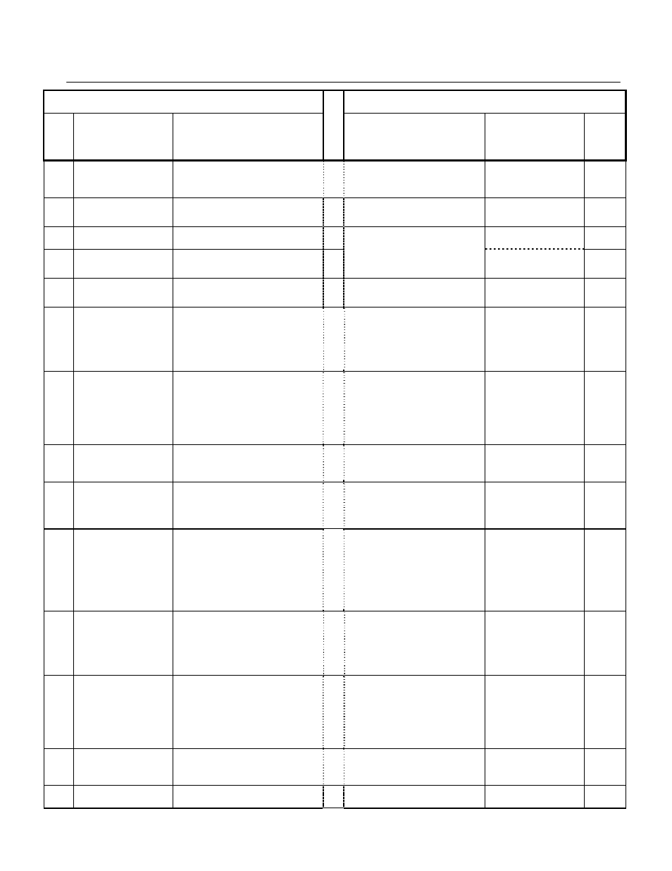
Appendix 3- Parameter Cross Reference
PL.F7.05 Page
52
of 54
GPD506/P5 Parameter
F7 Parameter
Param
No.
Nxxx
Parameter
Name
Description or Selection
Description or Selection
Parameter
Name
Param.
No.
096
Energy Saving
Selection
0: Energy saving disabled
1: Energy saving enabled
Energy Savings function enable/disable
selection.
0: Disabled
1: Enabled
Energy Saving Control
Selection
b8-01
097
Energy Saving
Gain K2
Set unit: 0.01 (It is 0.1 units in 100 or more)
Set range: 0.00-655.0
(Energy Saving disabled=0.00)
0.0 to 10.0
Sets energy savings control gain when in
vector control method.
Energy Saving Gain
b8-02
098
Energy Save Voltage Lower
limit @ 60 Hz
Set unit: 1%
Set range: 0-120%
Power Detection Filter Time
b8-05
099
Energy Save Voltage Lower
limit @ 6 Hz
Set unit:1%
Set range:0-25%
Used to fine-tune the energy savings
function when in V/F control method.
Search Operation Voltage
Limit
b8-06
100
Time of average
KW
Set unit:1 (1=25ms)
Set range: 1-200 (25ms=5.0sec)
0 to 2000
Used to fine-tune the energy savings
function when in V/F control method.
Power Detection Filter Time
b8-05
101
MEMOBUS timeout
detection
0: Timeout detection disabled.
1: Timeout detection enabled.
Enables or disables the communications
timeout fault (CE).
0: Disabled - A communication loss will
not cause a communication fault.
1: Enabled - If communication is lost for
more than 2 seconds, a CE fault will
occur.
Communication Fault
Detection Selection
H5-05
102
MEMOBUS Stop
method selection at
communication error (CE)
0: Deceleration stop
(Decelerate by deceleration time 1)
1: Coast stop
2: Deceleration stop
(Decelerate by deceleration time 2)
3: Continue operation (alarm display)
Selects the stopping method when a
communication timeout fault (CE) is
detected.
0: Ramp to Stop
1: Coast to Stop
2: Fast-Stop
3: Alarm Only
4: Run at d1-04
Stopping Method After
Communication Error
H5-04
103
MEMOBUS
Frequency reference unit
selection
0: 0.1Hz/1
1: 0.01Hz/1
2: 100%/30000
3: 0.1%/1
104
MEMOBUS
Slave address
Set unit:1 Set range:0-31
(There is no MEMOBUS communication at
set point =0)
0 to 20 Hex
Selects Drive station node number
(address) for Modbus terminals R+, R-, S+,
S-. The Drive’s power must be cycled for
the setting to take effect.
Drive Node Address
H5-01
105
MEMOBUS
Baud rate selection
0: 2400bps
1: 4800bps
2: 9600bps
Selects the baud rate for Modbus terminals
R+, R-, S+ and S-. The Drive’s power must
be cycled for the setting to take effect.
0: 1200 bps
1: 2400 bps
2: 4800 bps
3: 9600 bps
4: 19200 bps
Communication Speed
Selection
H5-02
106
MEMOBUS
Parity selection
0: Parity none
1: Even parity
2: Odd parity
Selects the communication parity for
Modbus terminals R+, R-, S+ and S-. The
Drive’s power must be cycled for the
setting to take effect.
0: No Parity
1: Even Parity
2: Odd Parity
Communication Parity
Selection
H5-03
107
Slip compensation
Gain
Set unit: 0.1%
Set range: 0.0-9.9%
(100%= maximum voltage frequency)
0.0 to 2.5
This parameter is used to increase motor
speed to account for motor slip by boosting
the output frequency.
If the speed is lower than the frequency
reference, increase C3-01.
If the speed is higher than the frequency
reference, decrease C3-01
Slip Compensation Gain
C3-01
108
Motor no-load current
Set unit: 1%
Set range: 0-99%
(100%= rated current of motor)
Set to the magnetizing current of the motor
as a percentage of full load amps (E2-01).
This value is automatically set during
rotational Auto-Tuning.
Motor No-Load Current
E2-03
109
Slip comp Primary
Delay Time Constant
Set unit: 0.1sec
Set range: 0.0-25 and 5sec
0 to 10000
This parameter adjusts the filter on the
Slip Compensation
Primary Delay Time
C3-02