Gpd506/p5, Product transition guide terminal comparison, Pl.f7.05 page – Yaskawa GPD 506/P5 to F7 User Manual
Page 18: Of 54
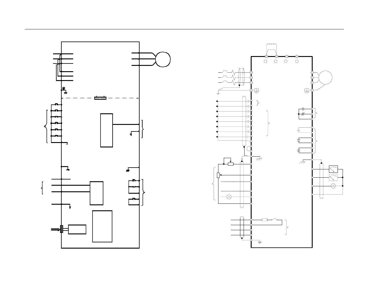
Product Transition Guide
Terminal Comparison
PL.F7.05 Page
18
of 54
T/L3
S/L2
R/L1
S3 (H1-01)
S2
S1
SC
E(G)
S4 (H1-02)
S5 (H1-03)
S6 (H1-04)
S7 (H1-05)
SN
S+
R-
R+
S-
IG
F7
W/T3
V/T2
U/T1
MC
MB
MA
M2
M1
M4
M3
E(G)
(H4-01) FM
(H4-04) AM
AC
(H2-01)
(H2-02)
Modbus RTU
Communications
RS-485/422
19.2 Kbps
E
xt
er
na
l F
req
ue
nc
y R
e
fe
re
n
ce
MCCB
L3
L2
L1
3-Phase
Power
Supply
50/60Hz
Reverse Run/Stop
Foward Run/Stop
Multi-function
Digital Inputs 3-8
24VDC, 8 mA
M
Motor
Digital
Output 1
Fault
Contact
250VAC,
30VDC,
1A
Multi-
function
Digital
Outputs 2-4
250VAC,
30VDC, 1A
+
-
+
-
Multi-function
Analog Outputs 1-2
0 to +/-10VDC, 2mA
4-20mA, 500
+/-9 Bit Resolution
+/- 8% Accuracy
110
Ω
Terminating
Resistor
S8 (H1-06)
M6
M5
(H2-03)
Ω
Digital Inputs 1-2
24VDC, 8mA
SP 24VDC
+V +15VDC +/-10%, 20mA
A1 0 to +/-10VDC, 20 k *
A2 4 to 20mA, 250 *
[0 to +/-10VDC, 20k **]
Multi-function Analog Input 1 (H3-09)
AC
Ω
Ω
Ω
2k
Ω
2k
A3 0 to +/-10VDC, 20k *
Multi-function Analog Input 2 (H3-05)
Ω
RP 0 to 32kHz, 5 to 12VDC, 3k ***
Multi-function Pulse Input (H6-01)
S1
-V -15VDC +/-10%, 20mA
Ω
(H6-06) MP
Multi-function
Pulse Output
0 to 32kHz
9VDC @ 3k
+/-5% Accuracy
Ω
* +/-11 Bit Resolution, 0.2% Accuracy
** 11 Bit Resolution, 0.2% Accuracy
*** +/-5% Accuracy
+ 1
+ 2
+ 3
-
Shorting Bar Standard:
CIMR-F7U20P4 to 2018
CIMR-F7U40P4 to 4018
DC Reactor Standard:
CIMR-F7U2022 to 2110
CIMR-F7U4030 to 4300
U
X
F7
Note: Drawing size does not
represent actual drive size.
D igital
RS-2 32
Serial Port
Analo g Inpu ts
(250Ω)
Operator
Input FI selectable
4~20 mA
or
0~10V
(10-pin)
S1 - Fixed
S2
S3
SC (Co m)
S4
S5
S6
FS
FV
FI
FC
PWM
8 bit
Multi-Function
Inputs
G
(+15V)
(20kΩ)
(0V)
0~+10V
4~20mA
0~10V
AM
(Com) AC
G
MA
MB
MC
M1
M2
Multi-Fu nction
Analog Outputs
Multi-Function
Relay Outp uts
A/D
10 bit
IM
L11
L21
L31
L1
L2
L3
T1
T2
T3
Gate Drive
GPD506/P5