Yaskawa GPD 506/P5 to F7 User Manual
Page 16
Product Transition Guide
GPD506/P5 to F7
PL.F7.05 Page
16
of 54
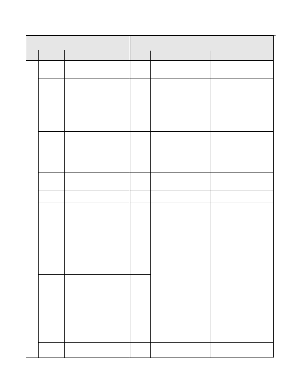
GPD506/P5 Terminal
F7 Terminal
(Designations similar to GPD506/P5)
Type
GPD506/P5
Terminal
Default Function & Description
F7
Terminal
Default Function
F7 Description
FS
+15V Power supply output for
analog command
(Allowable current, 20mA max.)
+V
+15Vdc power output
+15Vdc
(Max. current: 20mA)
–
–
-V
-15Vdc power output
-15Vdc
(Max. current: 20mA)
FV
Frequency reference input
(voltage) 0 to +10V/100%,
n043 = “FV=MSTR”:
FV enabled
n043 = “FI=MSTR”:
FI enabled
0 to +10V (20kW)
A1
Analog input or speed
command
0 to +10Vdc=100%
0 to +/-10Vdc =100%
(H3-01) (20k ohm)
FI
Frequency reference input
(current) 4 to 20mA/100%
n043 = “FV=MSTR”:
FV enabled
n043 = “FI=MSTR”:
FI enabled
4 to 20mA (250W)
A2
Add to terminal A1
4 to 20mA=100%/(250 ohms)
0 to +10Vdc=100%/(20k ohm)
Function set by H3-09.
A3
Aux. frequency reference 1
0 to +10Vdc=100%/(20k ohm)
0 to +/-10Vdc=100%
Function set by H3-05
FC
Common terminal 0V
AC
Analog common
–
Anal
og Input
Si
gnal
s
E(G)
Connection to shield sheath of
signal lead
E(G)
Shield wire, optional ground
line connection point
–
M1 M1
M2
During running (N.O. contact)
Closed when running.
Multi-function contact output
(n042)
Dry contact capacity:
250VAC 1A or less
30VDC 1A or less
M2
During run
(N.O. contact)
Form A Dry contacts capacity:
1 A max. at 250Vac
1 A max. at 30Vdc
Multi-function digital output.
Function set by H2-01.
–
–
M3
–
–
M4
Zero speed
(N.O. contact)
Form A Dry contacts capacity:
1 A max. at 250Vac
1 A max. at 30Vdc
Multi-function digital output.
Function set by H2-02.
–
–
M5
–
–
M6
Frequency agree
(N.O. contact)
Multi-function digital output.
Function set by H2-03.
MA MA
Dig
ital Ou
tp
ut
Sig
na
ls
MB
Fault contact output
(N.O./N.C. contact)
MB
Fault output signal
(SPDT)
Form C Dry contacts
capacity: