0 parameter changes, 3 group h terminal - function h1 digital inputs, 4 function h2 digital outputs – Yaskawa G5 Eliminator User Manual
Page 19: 5 function h4 analog outputs, 6 group f options
Date: 07/01/04, Rev: 04-07
Page 19 of 27
TM.G5SW.015
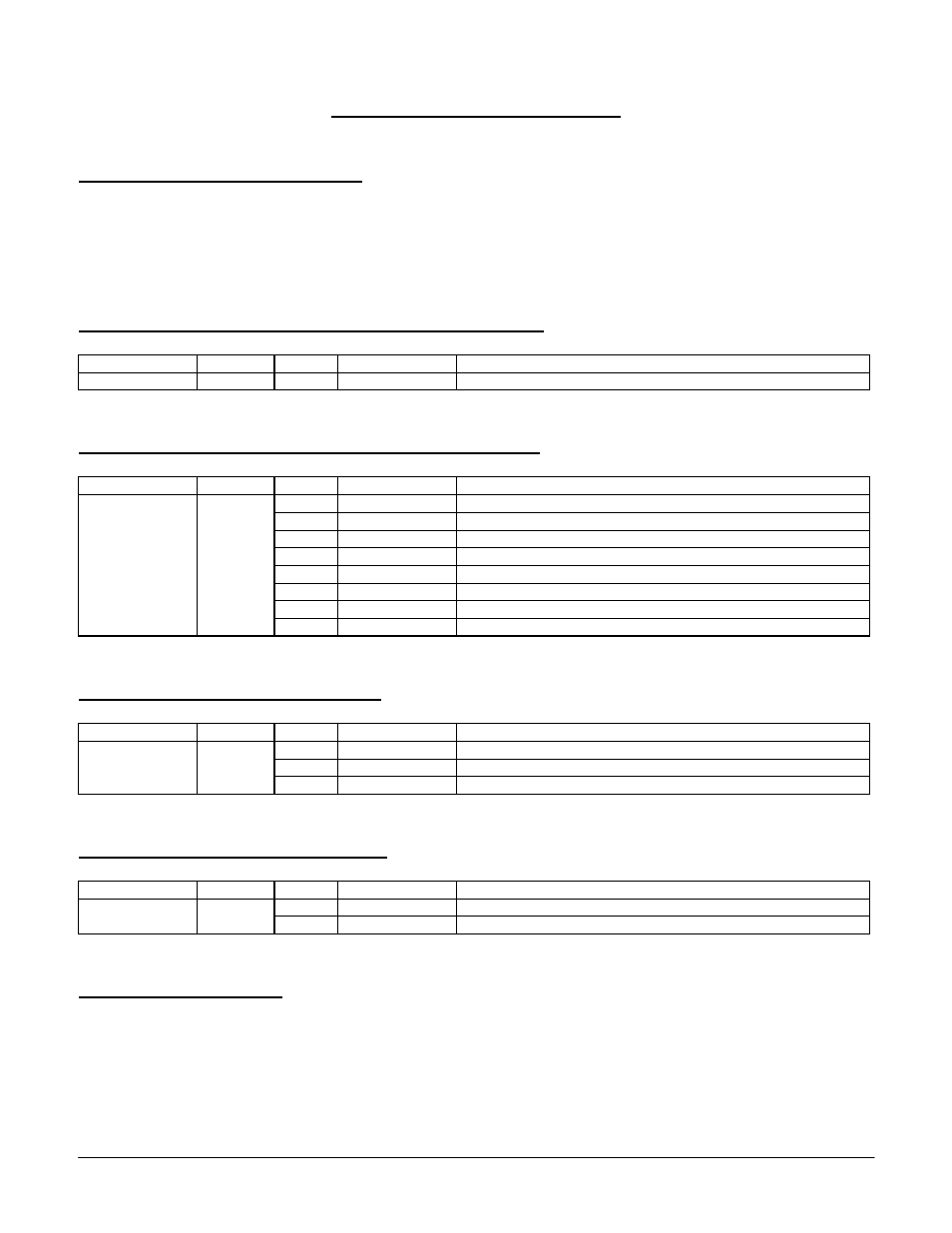
3.0 Parameter
Changes
3.1
Group A User Parameters
The user parameters are located within the “Initialize” menu selection. When the GPD515/G5
drive has been flashed with this software A2-11 through A2-32 constants are converted to the
parameters used to configure the drive.
3.2
Group b Applications – Function b1 Sequence
Display Constant
Setting
Display Description
Reference Source
b1-01
05
Eliminator Ref
Enables the Eliminator Software
3.3
Group H Terminal - Function H1 Digital Inputs
Display Constant
Setting
Display Description
80
Switch 1 DI
Switch function with a common output to a NO and NC input
81
Switch 2 DI
Switch function with a common output to a NO and NC input
82
MOP UP
Increases the MOP value
83
MOP DOWN
Decreases the MOP value
84
MOP RESET
Resets the MOP value to the default value set in parameter P2-05
85
Number Hold
Holds the last value input until de-activated
86
CASE DI 7
Reserved
Terminal 3 Sel
Terminal 4 Sel
Terminal 5 Sel
Terminal 6 Sel
Terminal 7 Sel
Terminal 8 Sel
H1-01
H1-02
H1-03
H1-04
H1-05
H1-06
87
CASE DI 8
Reserved
3.4
Function H2 Digital Outputs
Display Constant
Setting
Display Description
40
CONNECTION 80
Switch function with a common output to a NO and NC input
41
CONNECTION 81
Switch function with a common output to a NO and NC input
Terminal 9 Sel
Terminal 25 Sel
Terminal 26 Sel
H2-01
H2-02
H2-03
42
CONNECTION 82
Increases the MOP value
3.5
Function H4 Analog Outputs
Display Constant
Setting
Display Description
50
Case Monitor 1
Links the value in U1-50 to the selected analog output
Terminal 21 Sel
Terminal 23 Sel
H4-01
H4-04
51
Case Monitor 2
Links the value in U1-51 to the selected analog output
3.6
Group F Options
Constant F1-01, Pulses Per Rev is enabled in all control methods