Yaskawa G5 Eliminator User Manual
Page 15
Date: 07/01/04, Rev: 04-07
Page 15 of 27
TM.G5SW.015
output 61 = ((input 60 X P1-08) / P1-09) + P1-10
Function
Controls
Range
Default
Setup
P1-08 = Scale Multiplier
-9999 to 9999
0
P1-09 = Scale Divisor
-9999 to 9999
0
Scale
P1-10 = Scale Bias
-9999 to 9999
2.2.6 Center
Winder
The Center Winder Function calculates and outputs the ratio of line surface speed / winder
motor speed. This ratio can then be divided into the winder’s speed reference to control the
winder motor as the roll diameter increases or decreases. The actual roll diameter can be
calculated by multiplying the ratio by the core diameter. The diameter will be in the same units
as the core diameter. This is a simple center winder function and can be used only one time in
a configuration.
Input connector 20 should connect to the line speed. The line speed must be directly related to
the actual speed of the material being wound. Input connector 21 must be connected to the
winder’s motor speed. When the winder is at core input 20 should equal input 21. The
necessary adjustments must be made to make this a true statement.
The output to this function is filtered to avoid over reacting to sudden short changes in the input
information. Parameter P1-06 controls how fast the drive reacts to the diameter change.
Parameter P1-07 sets the maximum ratio that will be applied to the drive speed and is equal to
maximum roll diameter / core diameter. The ratio calculation will stop at the maximum ratio.
Function
Controls
Range
Default
Setup
P1-06 = Diameter Filter Time
0.1 to 50.0 sec
0.1
Center
Winder
P1-07 = Diameter Build Ratio
0.1 to 15.0
12.5
P1-07 = Max Roll Diameter / Core Diameter
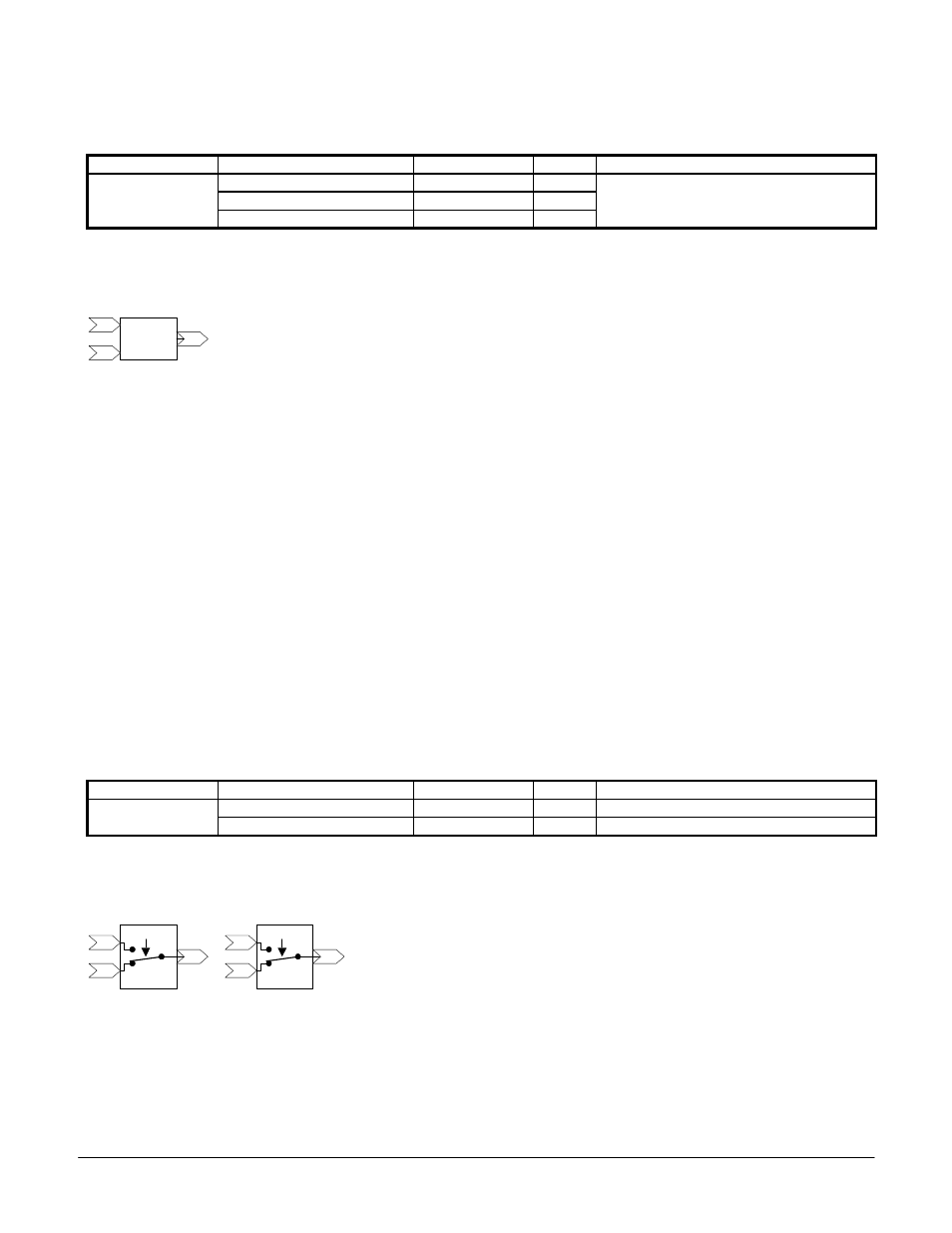
2.2.7 Switch
The switch function provides a means to switch between two possible inputs via a multi-function
input. Switch 1 connects input 02 to output 03 when the multi-function input is off or not
configured. Switch 1 connects input 01 to output 03 when the configured multi-function input is
turned on. Switch 2 connects input 05 to output 06 when the multi-function input is off or not
Figure 2.2.6
Center
Winder
22
20
21
Figure 2.2.7
03
01
02
Switch 1
H1-0? = 80
06
04
05
Switch 2
H1-0? = 81