Yaskawa G5 Eliminator User Manual
Page 17
Date: 07/01/04, Rev: 04-07
Page 17 of 27
TM.G5SW.015
The Drive Maximum Torque function sets or dynamically changes the maximum forward and
reverse torque value used by the drive. This control is only available when A2-01 = 3: flux
vector control mode. The forward and reverse torque values are equal when this function is
used.
2.3.3 Accel / Decel
The Accel / Decel function allows the acceleration and deceleration rates to be dynamically
adjusted. The change may be calculated using the following equations when the input is fixed.
Accel Time = (Input 19 x C1-01) / 10000
Decel Time = (Input 19 x C1-02) / 10000
When the input is 100.00% or 10000 the accel / decel rate will be C1-01 and C1-02.
2.3.4 Drive
Output
(contact and transistors)
Drive Output functions provide control to the three multi-function outputs. When the value
connected to the input exceeds the associated P2 parameter level the output will close. It will
open when the input drops below the set level.
Function
Information
Setup
Contact Output 9
Connects terminal 9 to 10
H2-01 = 40: CONNECTION 80, P2-07: Output 9 Level
Trans Output 25
Sinks terminal 25 to 27
H2-02 = 41: CONNECTION 81, P2-08: Output 25 Level
Trans Output 26
Sinks terminal 26 to 27
H2-03 = 42: CONNECTION 82, P2-09: Output 26 Level
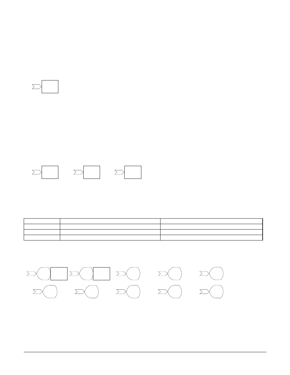
2.3.5 Monitor / Analog Output
Monitor functions provide a means to monitor values within a configuration. They can be used
at any time. Monitor functions do not require setup. The value input into a monitor is divided by
10, to increase the range of the monitor’s display.
Figure 2.3.3
Accel/
Decel
19
Figure 2.3.4
Drive
Output 41
81
Drive
Output 40
80
Drive
Output 42
82
Figure 2.3.5
U1-54
Monitor
94
U1-53
Monitor
93
U1-52
Monitor
92
U1-51
Monitor
91
Drive
Analog
Output 51
U1-50
Monitor
90
Drive
Analog
Output 50
U1-56
Monitor
96
U1-57
Monitor
97
U1-58
Monitor
98
U1-59
Monitor
99
U1-55
Monitor
95