Preventing noise interference, 7 troubleshooting – Yaskawa Option PG-F3 Motor Encoder Feedback User Manual
Page 40
7 Troubleshooting
40
YASKAWA ELECTRIC TOBP C730600 51F 1000-Series Option PG-F3 Installation Manual
◆
Preventing Noise Interference
Take the following steps to prevent erroneous operation caused by noise interference:
• Use shielded wire for the PG encoder signal lines.
• Limit the length of all motor output power cables to less than 20 m.
• The signal “Sensor Up” must be connected to terminal IP on the PG-F3 option for cables
longer than 10 m. Additionally, the “Sensor 0 V”must be connected to terminal IG.
• Use separate conduit or cable tray dividers to separate option control wiring, main circuit
input power wiring, and motor output power cables.
• Ground the shield on the PG encoder side and the drive side. If electrical inteference
problems arise in the PG encoder signal, verify that the shield is properly grounded and
ground one end of the signal line or remove the ground connection on both ends.
• Properly connect the shield in cable to the IG on the option terminal or remove the ground
connection on both ends.
■
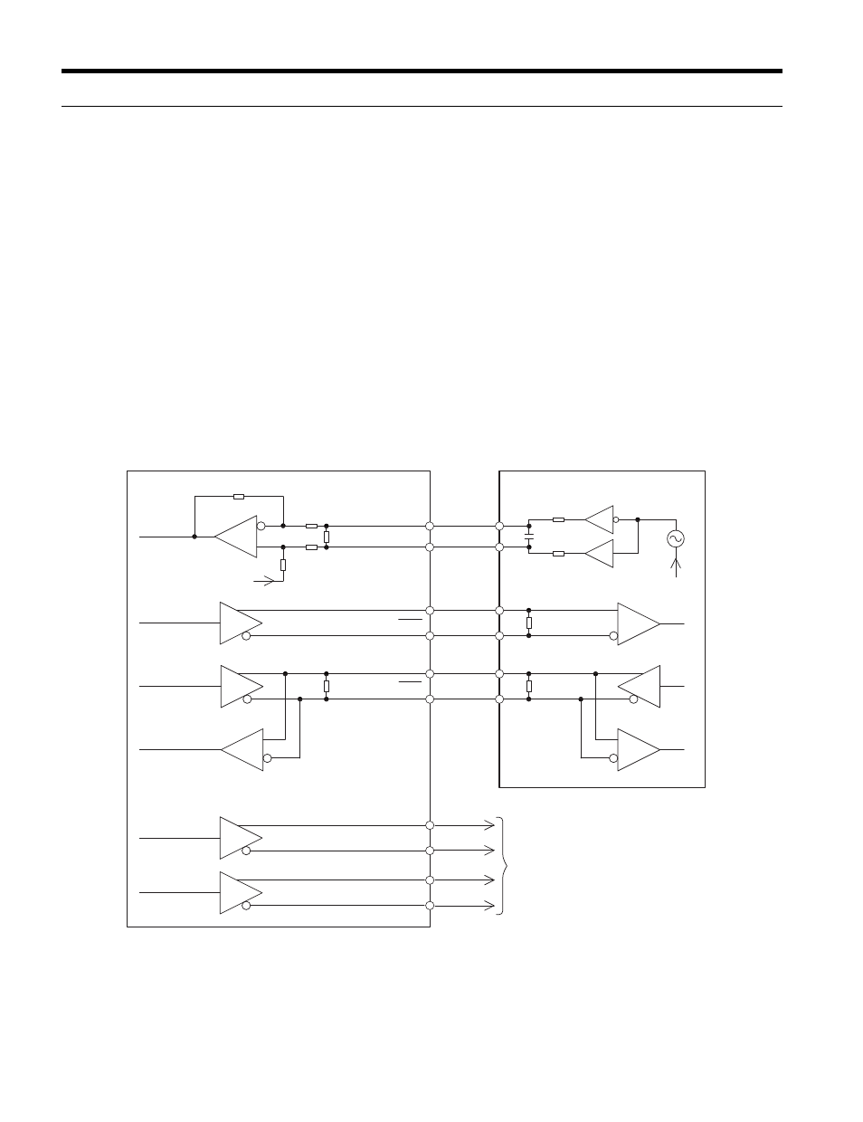
Interface Circuit
EnDat 2.1/01, EnDat 2.2/01
Figure 11
Figure 14 Interface Circuit (EnDat 2.1/01, EnDat 2.2/01)
120
Ω
120
Ω
PG-F3
CK
CK
DT
DT
a+
a
–
b+
b
–
2.5 V
PG Encoder
26LS31 Level
Clock
Data output
Data input
Monitor Signals
A
–
, B
–
A+, B+