Table 9, 5 installation procedure – Yaskawa Option PG-F3 Motor Encoder Feedback User Manual
Page 31
5 Installation Procedure
YASKAWA ELECTRIC TOBP C730600 51F 1000-Series Option PG-F3 Installation Manual
31
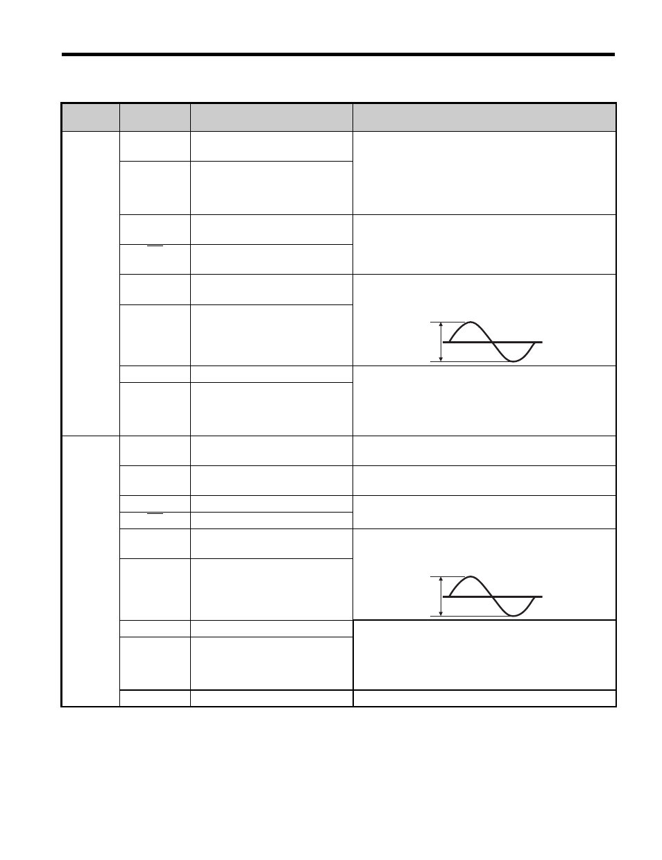
Table 9
Option Terminal Functions (HIPERFACE)
Terminal
Block
Terminal
(Signal)
Function
Description
TB1
IP
(Us)
PG encoder power supply
Supplies power to the PG encoder.
• Jumper with terminal CN3 to select the power
supply voltage, 5 V or 8 V.
• Voltage range:
5 V
±5%, 330 mA
8 V
±10%, 150 mA
IG
(GND)
PG encoder power supply
common
DT
(Data+)
Communication data signal I/O
Reads and processes PG encoder data.
Signal level: RS-485 protocol
DT
(Data-)
Inverse communication data
signal I/O
B+
(+SIN)
SIN signal input
Input for the sine-wave from the PG encoder.
• Maximum input frequency: 20 kHz
• Input signal differential: +SIN - REFSIN
B-
(REFSIN)
Inverse SIN signal input
b+
SIN pulse monitor signal output
Outputs a ratio of the sine pulse frequency.
• Output method: Line driver
• Output voltage: RS-422 level
• Possible resolution: 1/n (n = 0 to 32)
Set F1-06 to monitor the pulse signal.
b-
Inverse SIN pulse monitor signal
output
TB2
IP
(Us)
PG encoder power supply
Supplies power to the PG encoder.
Connects to terminal IP on the option.
IG
(GND)
PG encoder power supply
common
Supplies power to the PG encoder.
Connects to terminal IG on the option.
CK
–
Not used.
CK
–
A+
(+COS)
COS signal input
Input for the cosine-wave from the PG encoder.
• Maximum input frequency: 20 kHz
• Input signal differential: +COS - REFCOS
A-
(RSFCOS)
Inverse COS signal input
a+
COS pulse monitor signal output Outputs pulses of the cosine signal frequency ratio.
• Output method: Line driver
• Output voltage: RS-422 level
• Possible resolution ratio: 1/n (n = 0 to 32)
Set F1-06 to monitor the pulse signal.
a-
Inverse COS pulse monitor
signal output
FE
Ground
Ground terminal for shielded cable.
0.9 V to 1.1 V
0.9 V to 1.1 V