Table 5, 5 installation procedure – Yaskawa Option PG-F3 Motor Encoder Feedback User Manual
Page 24
5 Installation Procedure
24
YASKAWA ELECTRIC TOBP C730600 51F 1000-Series Option PG-F3 Installation Manual
Table 4 PG Encoder Cable Specification (HIPERFACE)
6.
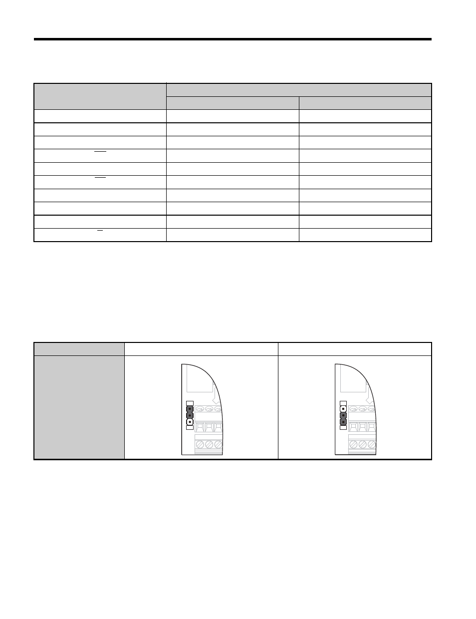
Set the voltage for the PG encoder power supply using jumper CN3 located on the
option. Position the jumper as shown in
to select the voltage level.
NOTICE: The positioning of jumper CN3 selects the PG encoder power supply voltage (5 V or 8 V). Select
the voltage level for the PG encoder connected to the option and motor. If the wrong voltage is selected, the
PG encoder may not operate properly or may become damaged as a result.
Table 5 Setting the PG Encoder Power Supply Voltage (IP) with Jumper CN3
Option Terminal
PG Encoder Cable
Color
PG Encoder Signal
IP
Red
Us
IG
Blue
GND
CK
–
–
CK
–
–
DT
Gray/Yellow
DATA+
DT
Green/Purple
DATA-
A+
Pink
+COS
A-
Black
REFCOS
B+
White
+SIN
B
Brown
REFSIN
Voltage Level
5 V ± 5% (default)
8 V ± 10%
Jumper CN3 Position
5 V
8 V
5 V
8 V