5 installation procedure – Yaskawa Option PG-F3 Motor Encoder Feedback User Manual
Page 27
5 Installation Procedure
YASKAWA ELECTRIC TOBP C730600 51F 1000-Series Option PG-F3 Installation Manual
27
9.
Set drive parameters in
for proper motor rotation.
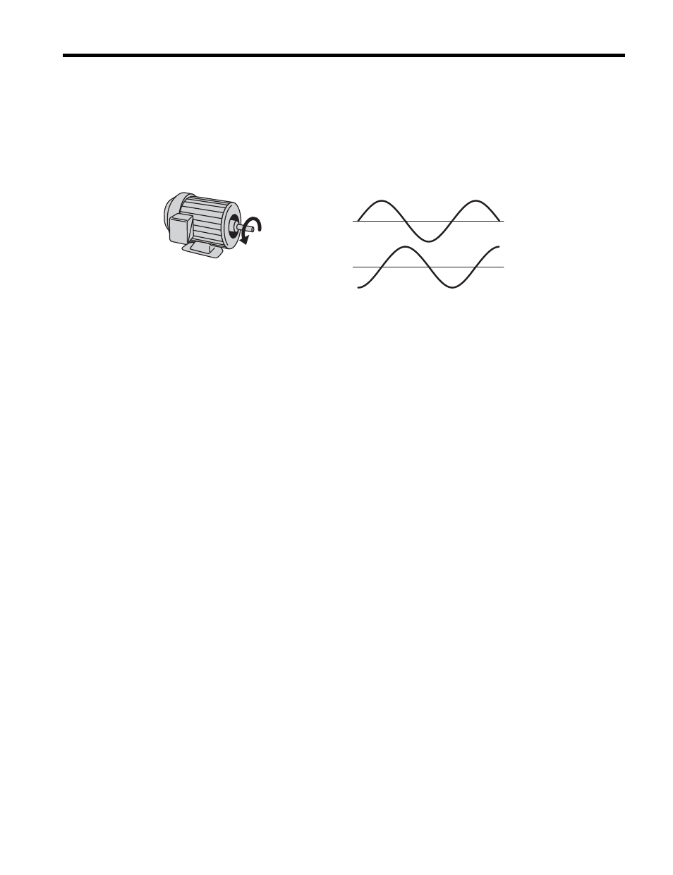
• Confirming Motor Rotation with EnDat 2.1/01, EnDat 2.2/01, or HIPERFACE
The leading pulse determines the motor rotation direction. A PG encoder signal with
leading A phase is considered to be rotating forward (counter-clockwise when viewing
rotation from motor load side).
Figure 10
Figure 13 Displacement of A and B Phases
After connecting the PG encoder outputs to the option, apply power to the drive and
manually rotate the motor and check the rotation direction by viewing monitor U1-05 on
the digital operator.
WARNING! Ensure the drive RUN circuit is locked out and a RUN command is not possible before
attempting to manually rotate the motor shaft with the drive powered on. Failure to comply may cause injury
to personnel due to inadvertant equipment movement.
Reverse motor rotation is indicated by a negative value for U1-05; forward motor rotation
is indicated by a positive value.
If monitor U1-05 indicates that the forward direction is opposite of what is intended, set
drive parameter F1-05 to 1 to switch the direction of how the option reads pulses from the
PG encoder output.
Note: If the drive is initialized using A1-03 =1110, 2220, or 3330, the value for F1-05 will reset to the
factory default and the parameter will need to be readjusted to switch the direction.
• Confirming Motor Rotation with EnDat 2.2/22
EnDat 2.2/22 uses serial data transmission and lacks A and B phases, so it is necessary to
refer to monitor U1-05 to determine the direction of rotation.
After connecting the PG encoder outputs to the option, apply power to the drive and
manually rotate the motor and check the rotation direction by viewing monitor U1-05 on
the digital operator.
WARNING! Ensure the drive RUN circuit is locked out and a RUN command is not possible before
attempting to manually rotate the motor shaft with the drive powered on. Failure to comply may cause injury
to personnel due to inadvertant equipment movement.
Reverse motor rotation is indicated by a negative value for U1-05; forward motor
rotation is indicated by a positive value.
If the motor is rotating forward, but U1-05 reads that it is rotating in reverse,
switch the rotation direction for the PG1 encoder by setting parameter F1-05 to 1.
Note: If the drive is initialized using A1-03 = 1110, 2220, or 3330, the value for F1-05 will reset to the
factory default and the parameter will need to be readjusted to switch the direction.
A
B
The A phase leads, followed
by the B phase displaced at 90 degrees
Time
→
Phase
Phase
F3