5 installation procedure – Yaskawa 1000 Series Drive Option - CANopen Installation User Manual
Page 19
5 Installation Procedure
YASKAWA ELECTRIC TOBP C730600 45B 1000-Series Option SI-S3 Installation Manual
19
3.
Prepare network cable connectors like explained in
on page
termination resistor like explained in
if the drive is the last node
in the network.
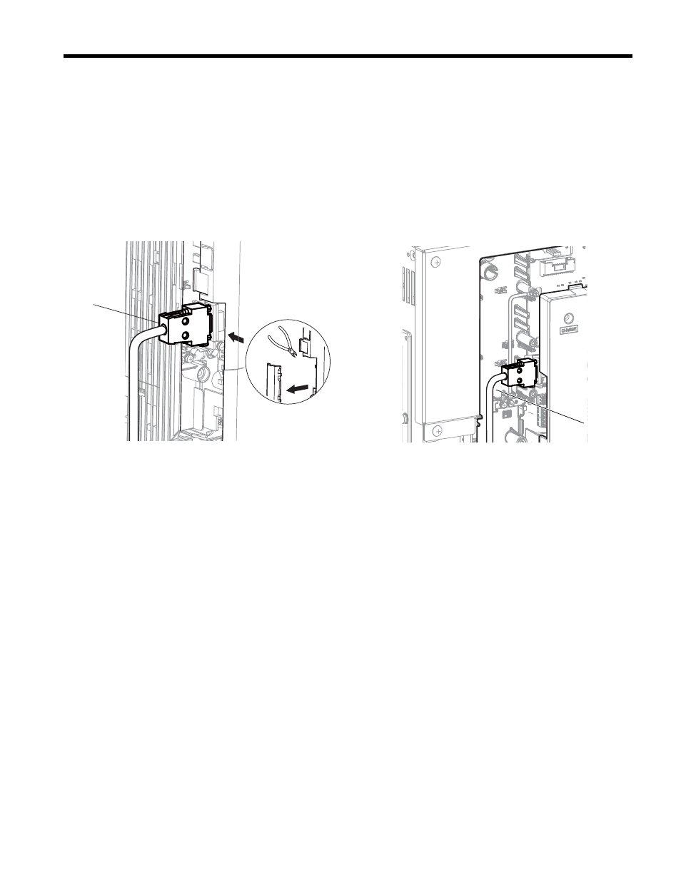
In the drives CIMR-A2A0004 to 0040 and 4A0002 to 0023 the network cable must
be routed to the outside through the drive top cover. Use a pair of wire cutters to cut
out the perforated openings at the left side of the top cover. Make sure no sharp
edges that can damage the cable remain.
Drives 2A0056 to 0211, 4A0031 to 0165 have enough space to keep all wiring
inside the unit.
Figure 6
Figure 6 Wiring space
4.
Plug in the network cable connector and fix it using the screws at the side of
connector.
5.
Place the front cover back onto the drive as it was before.
Note: 1. Take care when wiring the option card so that the front cover easily fits back onto the drive.
2. Install Cable Cover option to maintain the drive Enclosure Type.
6.
Attach the LED label packaged with the option card as shown in
.
7.
Switch on the drive power supply.
An “AEr” Alarm message indicating that the node address is set to 0 will appear on
the display. Set the node address in parameter F6-35. Set the communication
speed in parameter F6-36.
8.
Cycle the power supply to activate the changed settings. Installation completed.
A – Opening for cable lines
(CIMR-A2A0004 to 0040, 4A0002
to 0023)
B – Space for wiring
(CIMR-A2A0056 to 0211, 4A0031
to 0165)
B
A