SMA SB 3300-11 Installation User Manual
Page 36
Electrical Connection
SMA Solar Technology AG
36
SB33-38-11-IA-en-62
Installation Manual
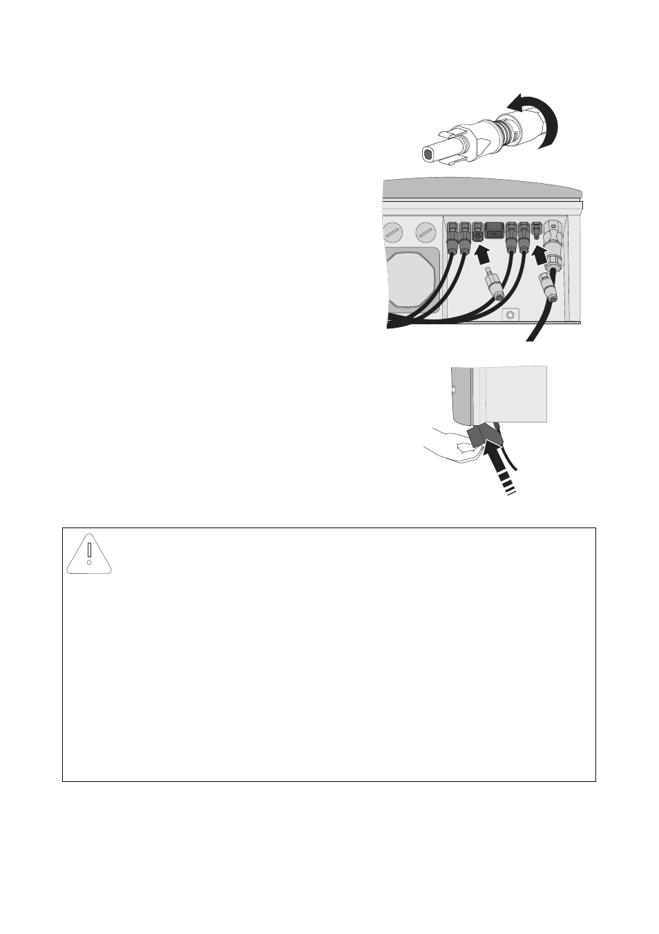
– Tighten the DC connector (torque: 2 Nm).
– Insert the DC connectors with sealing plugs into
the corresponding DC inputs on the inverter.
☑ The DC connectors click audibly into position.
7. Ensure that all DC connectors are securely in place.
8. If an Electronic Solar Switch is installed, check it for
wear, as described in section 8.3 "Checking the
Electronic Solar Switch for Wear" (page 49), and
reattach it firmly.
☑ The PV array is connected.
NOTICE!
Damage to the inverter due to moisture and dust intrusion
If the Electronic Solar Switch is not plugged in or incorrectly plugged in during operation,
moisture and dust can penetrate the inverter.
If the Electronic Solar Switch is not correctly plugged in, this can cause contacts to wear in
the Electronic Solar Switch or the Electronic Solar Switch might fall down. This can result in
yield loss and damage to the Electronic Solar Switch.
Always plug in the Electronic Solar Switch as described in the following:
• Do not tighten the screw in the Electronic Solar Switch.
• Firmly plug in the Electronic Solar Switch until it is flush with the enclosure.
• Ensure that the maximum distance between the Electronic Solar Switch and the
enclosure is 1 mm.
+