5 electrical connection, 1 safety, 2 overview of the connection area – SMA SB 3300-11 Installation User Manual
Page 21: 1 exterior view, Electrical connection, Safety, Overview of the connection area, Exterior view
SMA Solar Technology AG
Electrical Connection
Installation Manual
SB33-38-11-IA-en-62
21
5 Electrical Connection
5.1 Safety
5.2 Overview of the Connection Area
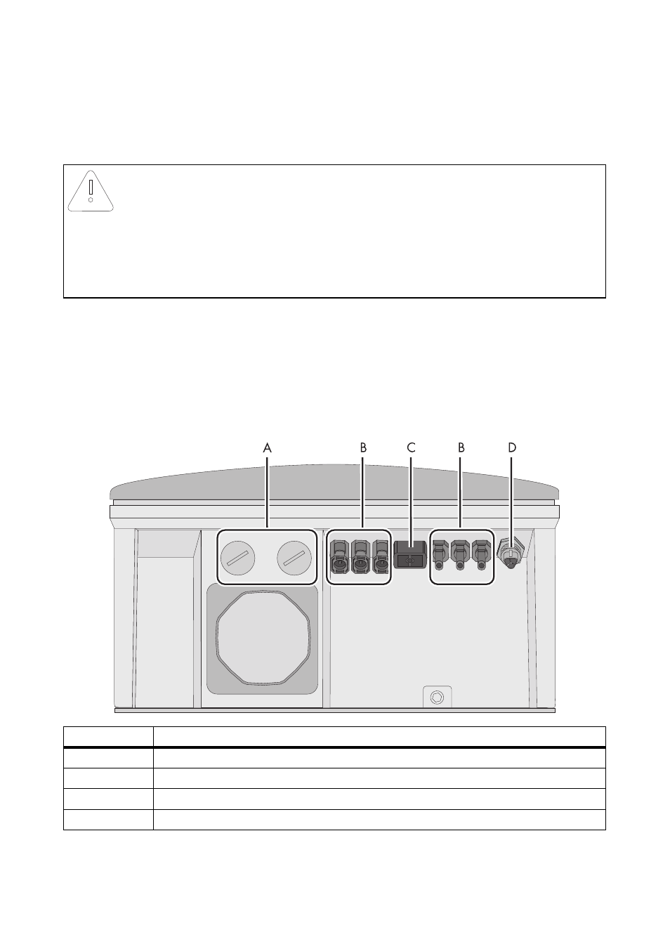
5.2.1 Exterior View
The following figure shows the assignment of the individual connection areas on the bottom of the
inverter.
*If you have ordered the inverter without ESS, the inverter is fitted with 2 negative and 2 positive DC connectors.
** optional
NOTICE!
Electrostatic discharges can damage the inverter.
Internal component parts of the inverter can be irreparably damaged by static electric
discharge.
• Before you touch a component inside the inverter, ground yourself by touching a
grounded object.
Object
Description
A
Enclosure openings for communication (with filler-plugs)
B
DC connectors for connecting the PV strings*
C
Jack for connecting the DC switch-disconnector Electronic Solar Switch (ESS)**
D
AC socket for grid connection