SMA SB 3300-11 Installation User Manual
Page 26
Electrical Connection
SMA Solar Technology AG
26
SB33-38-11-IA-en-62
Installation Manual
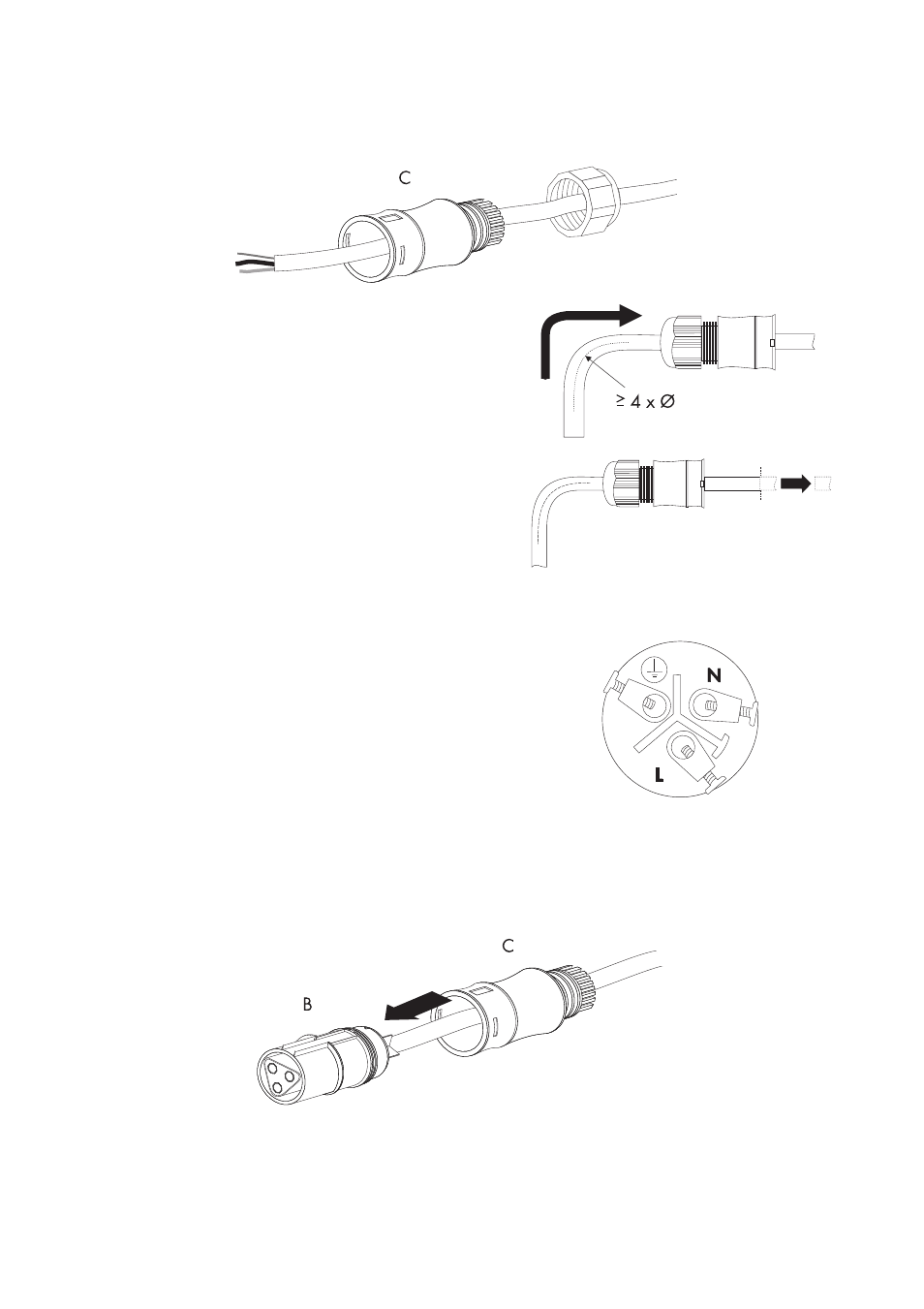
5. Pass the threaded sleeve (C) with the sealing ring over the AC cable.
6. Bend the AC cable. The bending radius must be at
least four times the cable diameter.
7. Shorten the cable.
8. Shorten phase L and neutral conductor N
4 to 5 mm.
9. Insert the PE protective conductor (green-yellow)
into the screw terminal with the earth sign on the
socket element and tighten the screw.
The PE protective conductor must be longer than the
insulated conductors of N and L.
10. Insert the neutral conductor N (blue) into the screw
terminal N on the jack element and tighten the
screw.
11. Insert phase L (brown or black) into screw terminal
L on the jack element and tighten the screw.
12. Make sure the insulated conductors are securely
connected.
13. Push the threaded sleeve (C) onto the jack element (B) until it audibly snaps into place.