4 pv array connection (dc), Pv array connection (dc) – SMA SIC 50 User Manual
Page 22
Electrical Connection
SMA Solar Technology AG
22
SIC50-IA-en-11
Installation Guide
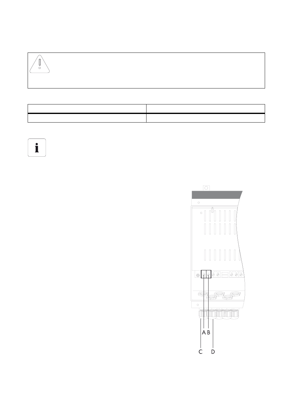
6.4 PV Array Connection (DC)
The following threshold values at the DC input of the charge controller may not be exceeded:
Connection Procedure
1. Unscrew the lock nut of the metric-thread cable
gland (C) and slide it along the PV array's "PV+"
cable.
2. Route the "PV+" cable of the PV array through the
cable gland into the charge controller and connect
it to the "PV+" connection terminal (A).
3. Retighten the lock nut of the cable gland.
4. Unscrew the lock nut of the metric-thread cable
gland (D) and slide it along the PV array's "PV-"
cable.
5. Route the "PV-" cable of the PV array through the
cable gland into the charge controller and connect
it to the "PV-" connection terminal (B).
6. Retighten the lock nut of the cable gland.
NOTICE!
Improperly connecting the charge controller to the PV array may irreparably
damage it.
• Never connect several charge controllers in parallel on the side of the PV array.
Maximum input voltage
Maximum input current
140 V (DC)
40 A (DC)
Sectioning point between PV array and charge controller
The DIN VDE 0100-712 standard stipulates that an all-pole sectioning point must be
installed between the PV array and the charge controller. Observe this standard as well as
all standards and guidelines that apply at the installation location for connecting the PV
array.