4 dc connection, 1 requirements for the dc connection, Dc connection – SMA STP 15000TL User Manual
Page 29: Requirements for the dc connection
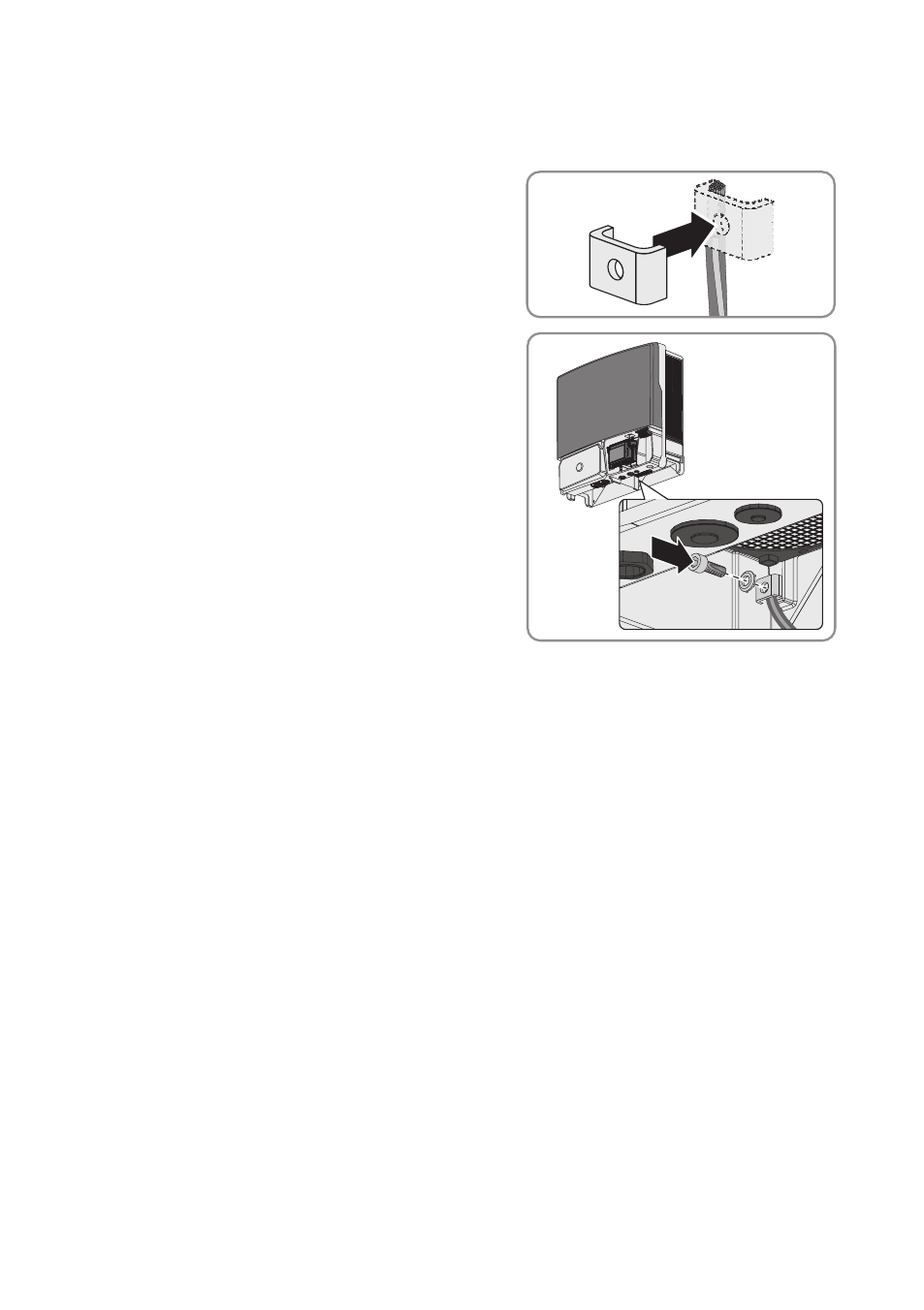
Procedure:
1. Strip the grounding cable insulation.
2. Lead the clamping bracket over the grounding
cable. Arrange the grounding cable on the left-
hand side.
3. Screw the clamping bracket tight using the
M6x16 cylindrical screw and the conical spring
washer M6 (torque: 6 Nm). The teeth of the
conical spring washer must face the clamping
bracket.
6.4
DC Connection
6.4.1
Requirements for the DC Connection
Requirements for the PV modules per input:
☐ All PV modules must be of the same type.
☐ All PV modules must be aligned and tilted identically.
☐ On the coldest day based on statistical records, the open-circuit voltage of the PV array must
never exceed the maximum input voltage of the inverter.
☐ The same number of series-connected PV modules must be connected to each string.
☐ The maximum input current per string must be maintained and must not exceed the through-
fault current of the DC connectors (see Section 11 "Technical Data", page 50).
☐ The thresholds for the input voltage and the input current of the inverter must be adhered to
(see Section 11 "Technical Data", page 50).
☐ The positive connection cables of the PV modules must be fitted with the positive DC
connectors (for information on assembling DC connectors, see the DC connector installation
manual).
☐ The negative connection cables of the PV modules must be fitted with the negative DC
connectors (for information on assembling DC connectors, see the DC connector installation
manual).
6 Electrical Connection
SMA Solar Technology AG
Operating Manual
29
STP15-17TL-10-BE-en-10