Figure 34 battery cabinet interconnection, Table 16 liebert -supplied interconnect wiring, Table 16 – Emerson 60HZ User Manual
Page 53: Liebert -supplied interconnect wiring
Installation Drawings
47
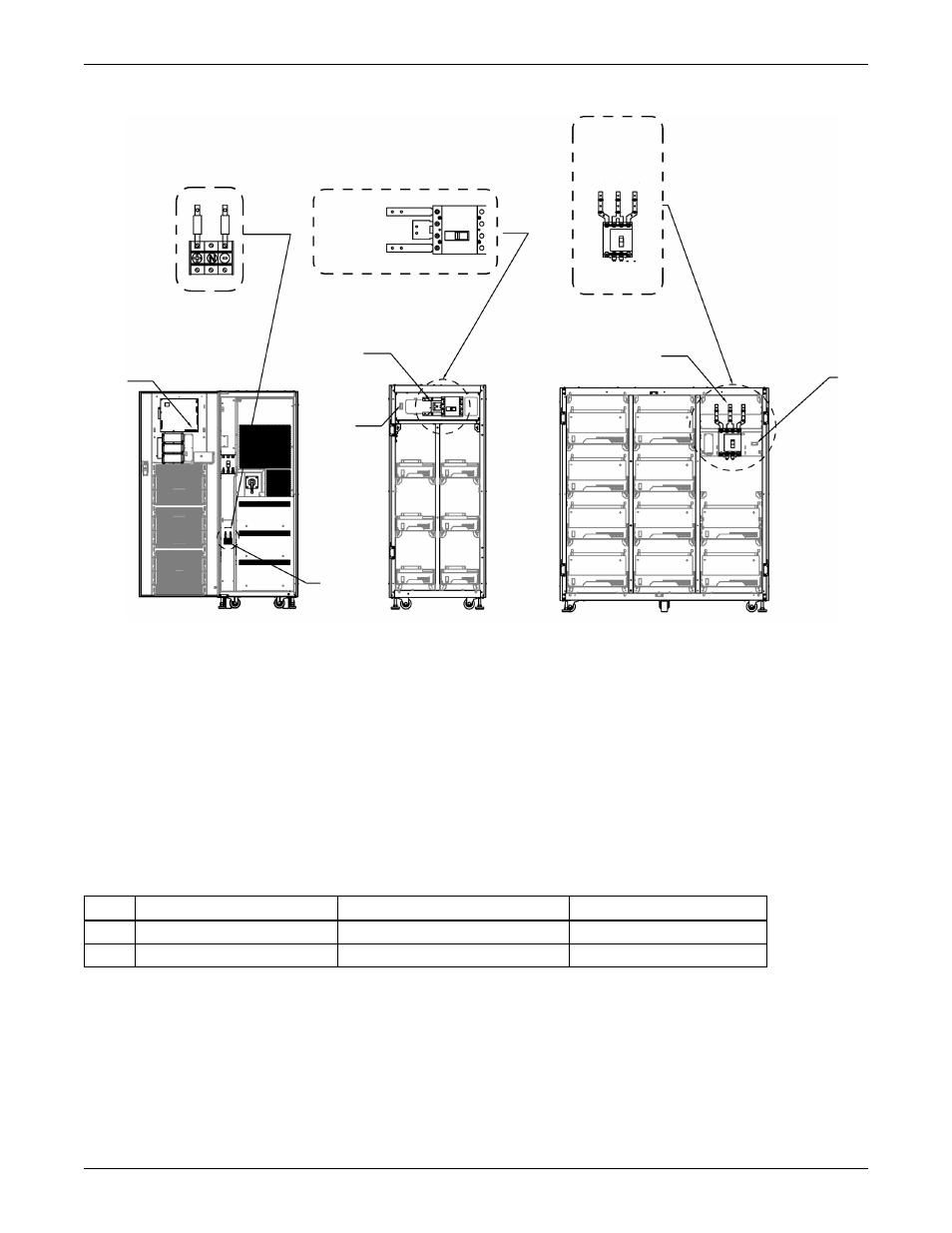
Figure 34 Battery cabinet interconnection
Table 16
Liebert -supplied interconnect wiring
Run
From
To
Conductors
A
UPS battery terminal block
External 27" or 59" battery cabinet
Positive, midpoint, negative
B
Battery cabinet terminal block
UPS monitor board
Battery breaker aux contacts
Refer to Table 16 for key to interconnection
UPS Module
Front View
with doors removed
27" Battery Cabinet
Front View
without doors and
protective plates
59" Battery Cabinet
Front View
without doors and
protective plates
Connection
Detail
Breaker
Detail
Breaker
Detail
Po
s
iti
ve
(+
)
Mi
d
p
o
int (N)
N
e
g
a
ti
ve
(-
)
Positive (+)
Midpoint (N)
Negative (-)
A
B
B
A
OR
B
A
NOTES:
1. All Liebert-supplied cable must be repositioned prior to and while the cabinets are being placed in
their final installed location.
2. All interconnection hardware supplied by Liebert
3. All interconnection cables supplied by Liebert when bolted together.
4. Interconnection cables field-supplied when battery cabinets are stand-alone.
5. Refer to the individual drawing of each piece of equipment for additional details.