Definition of a normalized vector – HEIDENHAIN TNC 640 (34059x-04) User Manual
Page 456
Programming: Multiple Axis Machining
12.6 Three-dimensional tool compensation (software option 2)
12
456
TNC 640 | User's Manual
HEIDENHAIN Conversational Programming | 3/2014
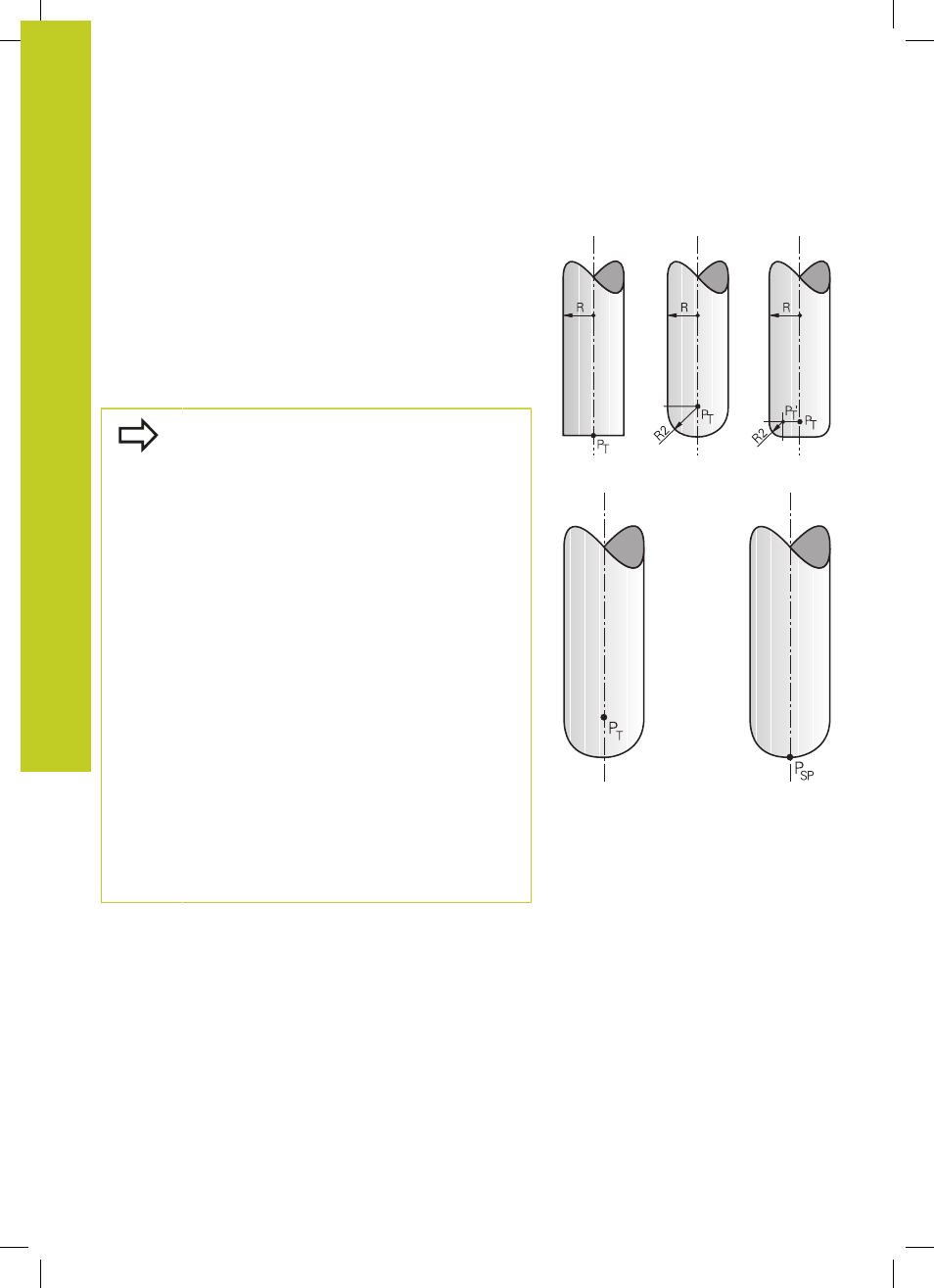
Definition of a normalized vector
A normalized vector is a mathematical quantity with a value of 1
and any direction. The TNC requires up to two normalized vectors
for LN blocks, one to determine the direction of the surface-normal
vector, and another (optional) to determine the tool orientation
direction. The direction of a surface-normal vector is determined
by the components NX, NY and NZ. With an end mill and a radius
mill, this direction is perpendicular from the workpiece surface
to be machined to the tool datum PT, and with a toroid cutter
through PT‘ or PT (see figure). The direction of the tool orientation
is determined by the components TX, TY and TZ.
The coordinates for the X, Y, Z positions and the
surface-normal components NX, NY, NZ, as well as
TX, TY, TZ must be in the same sequence in the NC
block.
Always indicate all of the coordinates and all of the
surface-normal vectors in an LN block, even if the
values have not changed from the previous block.
TX, TY and TZ must always be defined with
numerical values. You cannot use Q parameters.
Calculate the normal vectors as exactly as possible
and output them with a sufficient number of decimal
places, in order to avoid interruptions in the feed rate
during machining.
3-D compensation with surface-normal vectors is
only effective for coordinates in the main axes X, Y, Z.
If you insert a tool with oversize (positive delta value),
the TNC outputs an error message. You can suppress
the error message with the M function
M107 (See
"Definition of a normalized vector", page 456).
The TNC will not display an error message if an
entered tool oversize would cause damage to the
contour.
Machine parameter
toolRefPoint defines whether
the CAD system has calculated the tool length
compensation from the center of sphere PT or the
south pole of the sphere PSP (see figure).