Non-heidenhain devices – HEIDENHAIN iTNC 530 (340 49x-04) ISO programming User Manual
Page 670

670
14 Tables and Overviews
14.2 Pin La
y
out and Connecting Cable f
o
r the D
a
ta Int
e
rf
aces
Non-HEIDENHAIN devices
The connector pin layout of a non-HEIDENHAIN device may differ
considerably from that on a HEIDENHAIN device, depending on the
unit and type of data transfer.
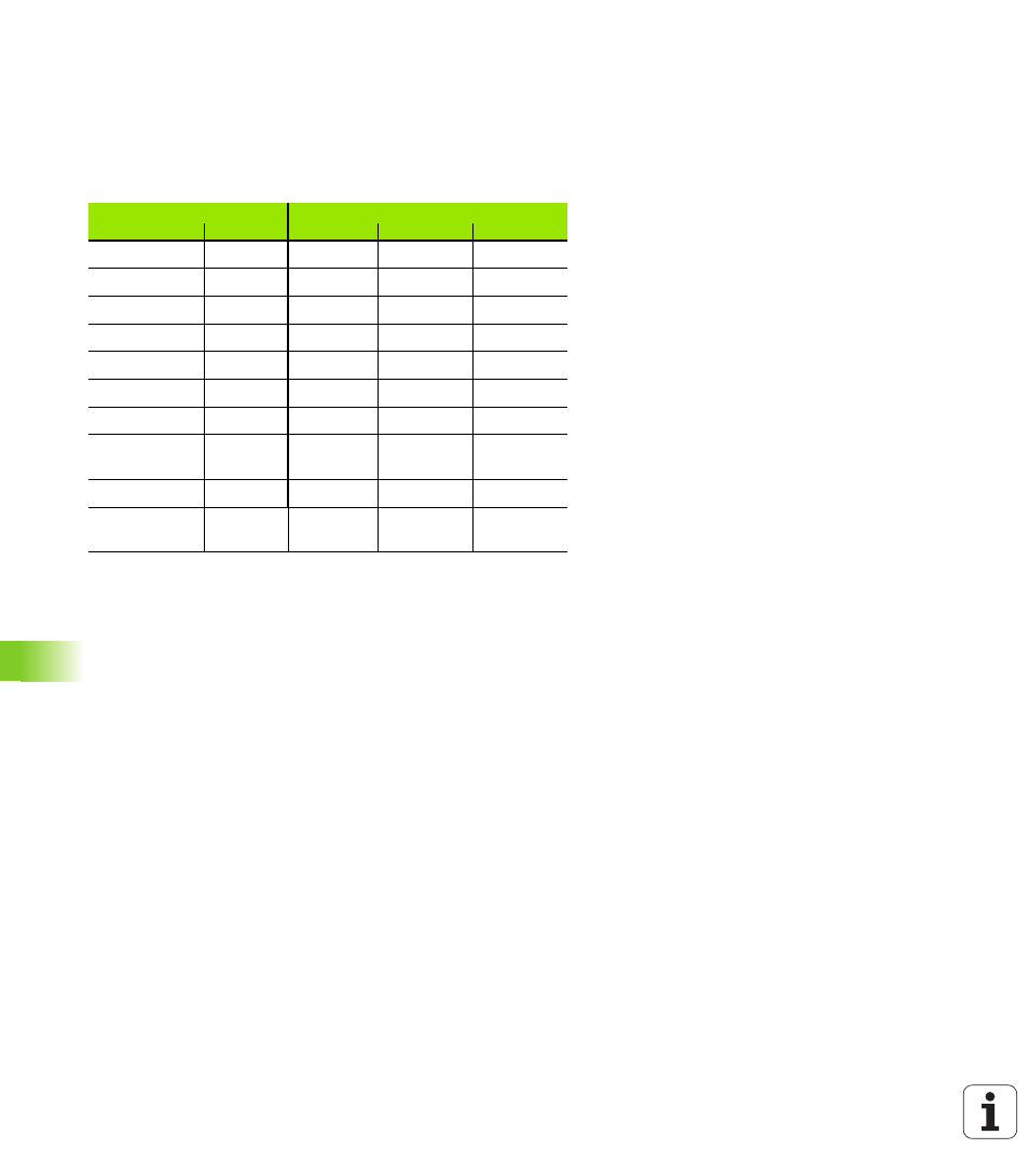
It depends on the unit and the type of data transfer. The table below
shows the connector pin layout on the adapter block.
Adapter block 363 987-02
VB 366 964-xx
Female
Male
Female
Color
Female
1
1
1
Red
1
2
2
2
Yellow
3
3
3
3
White
2
4
4
4
Brown
6
5
5
5
Black
5
6
6
6
Violet
4
7
7
7
Gray
8
8
8
8
White/
Green
7
9
9
9
Green
9
Hsg.
Hsg.
Hsg.
External
shield
Hsg.
See also other documents in the category HEIDENHAIN Equipment:
- TNC 122 User Manual (63 pages)
- TNC 122 Technical Manual (70 pages)
- TNC 360 Service Manual (157 pages)
- TNC 416 Technical Manual (510 pages)
- TNC 335 Technical Manual (581 pages)
- TNC 360 User Manual (237 pages)
- TNC 360 ISO-Programmierung (2 pages)
- TNC 415 (280 540) User Manual (227 pages)
- TNC 370D (92 pages)
- TNC 416 (289 pages)
- TNC 415 (280 540) Technical Manual (752 pages)
- TNC 415 (259 96x) Service Manual (195 pages)
- TNC 407 (280 580) User Manual (376 pages)
- iTNC 530 (340 420) Pilot (104 pages)
- TNC 407 (280 580) ISO Programming (333 pages)
- TNC 415 (280 540) Service Manual (252 pages)
- PT 880 Installation (112 pages)
- ND 100 User Manual (116 pages)
- ND 287 User Manual (147 pages)
- ND 280 Quick Start (12 pages)
- ND 200 (156 pages)
- ND 282 (10 pages)
- ND 287 Quick Start (26 pages)
- ND 282 B (39 pages)
- ND 281 A (44 pages)
- ND 281 B v.1 (53 pages)
- ND 281 B v.2 (65 pages)
- ND 221 v.2 (10 pages)
- ND 231 B v.2 (56 pages)
- ND 231 B v.1 (44 pages)
- ND 221 B v.2 (45 pages)
- ND 550 v.2 (8 pages)
- NDP 560 (10 pages)
- ND 523 (93 pages)
- ND 570 (8 pages)
- ND 750 v.2 (46 pages)
- ND 760 v.3 (72 pages)
- ND 770 v.1 (40 pages)
- ND 770 v.3 (41 pages)
- ND 760 E (44 pages)
- IOB 49 (21 pages)
- NDP 960 (68 pages)
- ND 780 Installation (132 pages)
- ND 970 (47 pages)
- ND 1100 Quick Start (36 pages)
