Setup – HEIDENHAIN ND 1300 Quick Start User Manual
Page 5
3
2. Calibrate optical edge detection
Teaching the edge detector calibrates
it to correctly recognize dark to light
transitions. Perform a TEACH calibration
after each startup, when lighting
changes, when the part changes and
when the magnification level changes.
• Touch the TEACH button.
• Follow the instructions shown on the
screen to complete the calibration.
3. Calibrate crosshair offset
Crosshair offset calibration compensates
for the location differences between the
center of the crosshairs and the edge
detector. Crosshair offset calibration is
only necessary when crosshairs and
edge detection will be used to probe
points on the same part.
• Touch the CROSS CAL button.
• Follow the instructions shown on the
screen to complete the calibration.
Final setup for video and edge
options
1. Calibrate error correction
Linear (LEC), segmented linear (SLEC)
and nonlinear (NLEC) error correction
methods can be used to compensate
for encoder and machine errors.
Refer to the ND 1300 User Guide for
instructions.
2. Calibrate stage squareness
This calibration is not necessary when
NLEC error correction is used.
• Align the squareness calibration
artifact to the reference axis.
• Measure the artifact angle. Refer to
the angle measurement instructions
later in this document if necessary.
• Display the SETUP MENU and then
touch the SQUARENESS menu item.
• Enter the measured angle into the
OBSERVED ANGLE field and then
enter the certified artifact angle into
the STANDARD ANGLE field.
• Press the FINISH key to complete the
calibration.
Note:
Many more setup functions are available
beyond the minimum parameters
discussed here. Refer to the ND 1300
User Guide for detailed instructions.
3. Add camera magnifications
When video systems include more
than one magnification, additional
magnification positions must be added
and calibrated.
• Return to the setup menu and touch
the MAGNIFICATIONS menu item
to dsplay the MAGNIFICATIONS
SCREEN.
• Touch the NEW button to add a
new magnification. A new BUTTON
LABEL number will be added. This
label will be available on the DRO
screen during measurements.
• The BUTTON LABEL can be changed
to any 3 character string. Touch the
BUTTON LABEL field and enter a
new label if desired.
4. Calibrate magnifications
Use a circle calibration artifact to
calibrate magnifications.
• Touch the ID number in the
MAGNIFICATIONS setup screen
to show the desired magnification
BUTTON LABEL.
• Touch the ARTIFACT DIAMETER field
and enter the artifact diameter.
• Touch the TEACH button and follow
the instructions shown on the screen.
• Repeat this process for all
magnifications.
5. Calibrate camera skew
• Touch the VED setup menu item and
then touch the CAL button.
• Follow the instructions shown on the
screen.
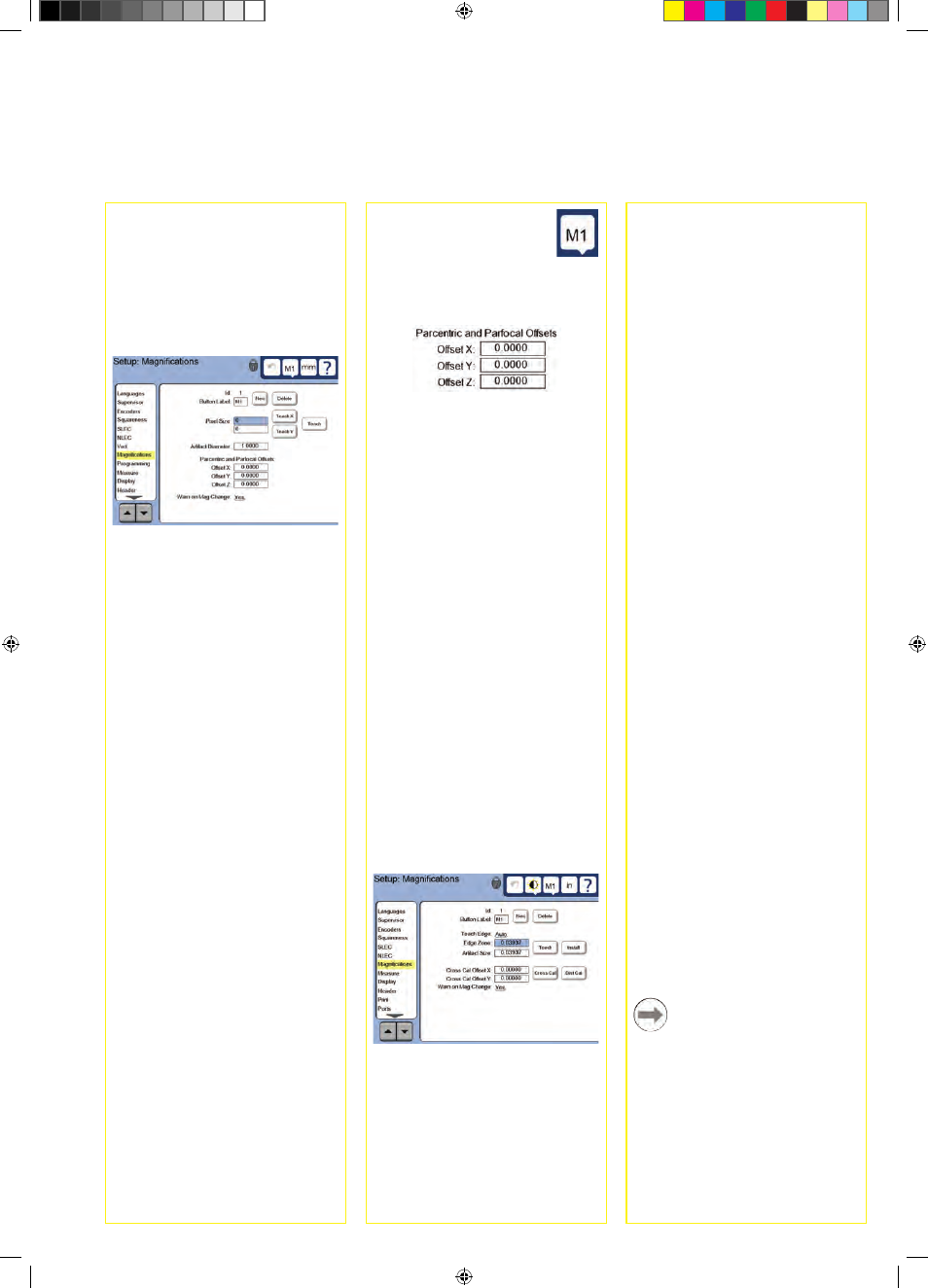
6. Calibrate parcentric and parfocal
alignment
This calibration eliminates X and Y
axis offset errors that can occur when
changing video magnifications. Use
a circle calibration artifact for this
calibration.
• Touch the MAGNIFICATIONS setup
menu item.
• Touch the MAGNIFICATION
icon to display the
magnification choices, then
select the highest level of
magnification.
• Enter zeros for the PARCENTRIC and
PARFOCAL OFFSETS.
• Repeat to zero the offsets of all
magnifications.
• Select the highest level of
magnification again.
• Measure the circle artifact and create
a zero datum on the circle center
point. Refer to the descriptions of
circle measurement and zero datum
creation later in this document if
necessary.
• Select the next lower level of
magnification and measure the
same circle artifact. Make a note of
the X, Y and Z positions shown in
the measurement results for this
magnification.
• Enter the X, Y and Z positions into the
OFFSET fields for this magnification.
• Repeat this process to enter OFFSET
values for all levels of magnification.
Setup for the optical edge
option
1. Add comparator magnifications
When coparator systems include more
than one magnification, additional
magnification positions must be added.
• Touch the MAGNIFICATIONS menu
item to dsplay the MAGNIFICATIONS
SCREEN.
• Touch the NEW button to add a
new magnification. A new BUTTON
LABEL number will be added. This
label will be available on the DRO
screen during measurements.
• The BUTTON LABEL can be changed
to any 3 character string. Touch the
BUTTON LABEL field and enter a
new label if desired.
Setup