Id button – Grass Valley Fiber Media Converter User Manual
Page 35
Media Converters — Instruction Manual
35
Installation and Operation
gives the different LED color conditions for a TX and RX module.
ID Button
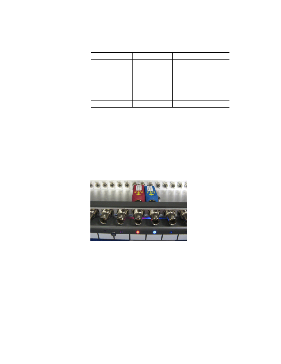
Pressing and holding the ID button (shown in
light the LEDs corresponding to channels populated with media con-
verters. The type of module installed will be reported on the front panel
LEDs. Blue indicates a receiver module and red indicates a transmitter
module as shown in
.
Figure 25. Module Status LEDs (ID button Held Down)
Table 2. VMC and MVMC TX LED Conditions (in Frame)
Status
TX (transmitter)
RX (receiver)
Green
Normal operation
Normal operation
Red
Transmit fault
Optical input signal out of range
Orange
N/A
Re-clocker not locked (VMC only)
Blinking Green
No cable connected
Loss of signal (no optical input)
Blinking Red
DDMI alarm
1
1
For DDMI (Digital Diagnostics Monitoring Interface) information, refer to
.
DDMI alarm
1
Blinking Orange
DDMI warning
DDMI warning
Blinking Blue
Power short on module
Power short on module