Frame monitoring, Module status leds – Grass Valley Fiber Media Converter User Manual
Page 34
34
Media Converters — Instruction Manual
Installation and Operation
Frame Monitoring
Once you have finished installation of all modules and cabling and the unit
is powered up, you can monitor the status of the frame and each installed
VMC and VMCR from the front panel of the frame.
The front panel (
) of the VMCR has 18 LEDs (one per channel)
which display the status (and type of module) of the modules installed, two
LEDs for displaying the status of the power supplies and one LED for dis-
playing frame temperature status.
The front panel also has a momentary ID switch which turns off the power
supply and temperature LEDs and changes the per-channel LEDs to indi-
cate the type of module installed on that BNC. Below each channel status
LED is an ID strip that can be labeled using a dry erase marker for identi-
fying information about the channel. Each of these functions are described
in detail in this section.
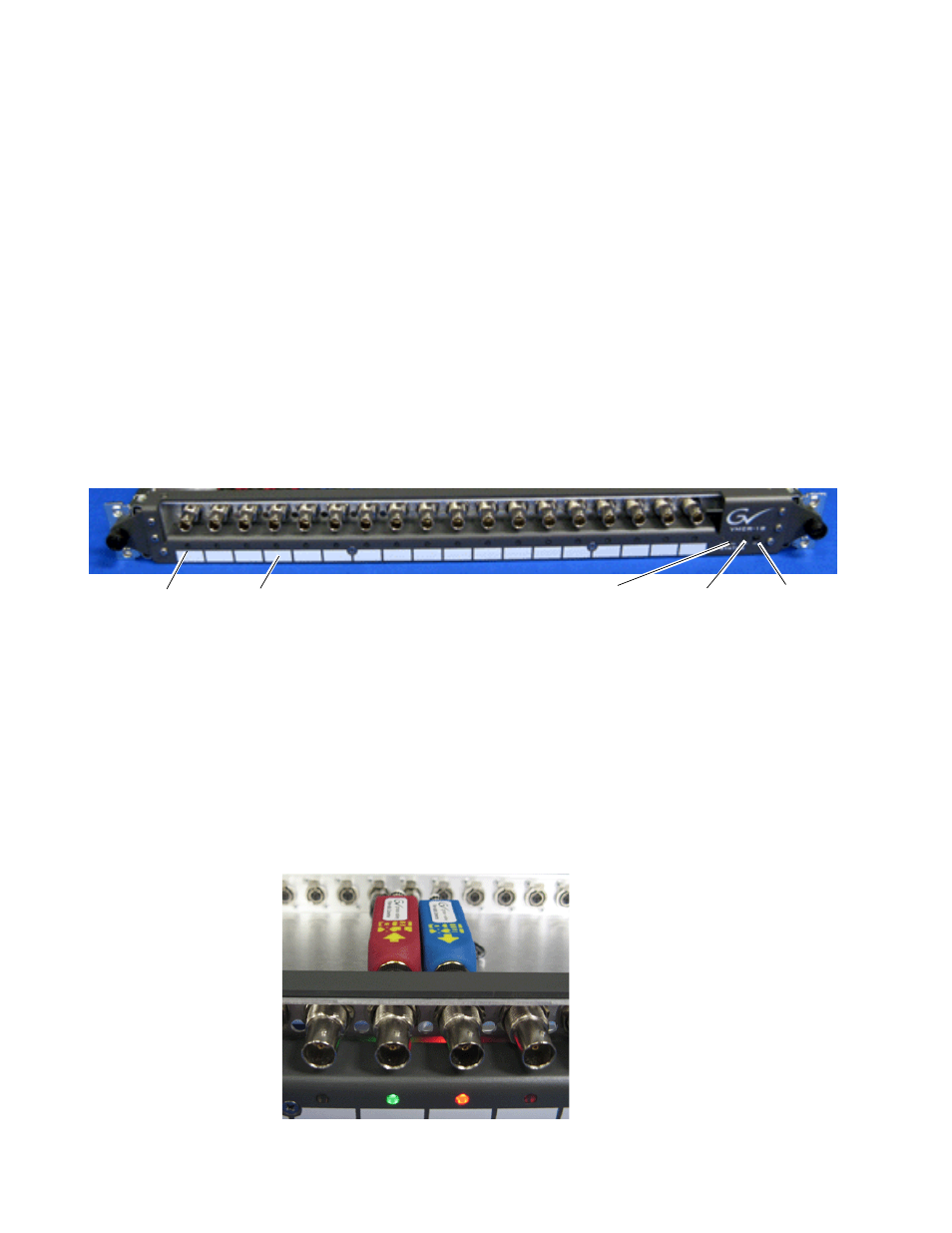
Figure 23. Front Panel Overview
Module Status LEDs
The front panel has 18 LEDs corresponding to each channel in the frame.
There are multi-colored/multi-function LEDs that can indicate the type of
module installed and the signal status of each channel.
During normal operation (ID button not pressed), each LED will show the
signal status of an installed channel (
). The meanings of the LED
states for the TX and RX are given in
.
Figure 24. Module Status LED (Normal Operation)
Status LEDs
ID button
Dry erase marker ID strip
Power Supply
Status LEDs
Temperature LED