Grass Valley Fiber Media Converter User Manual
Page 26
26
Media Converters — Instruction Manual
Installation and Operation
Each power input has a user-replaceable fuse located below the plug recep-
tacle. If the fuse needs to be replaced, first remove power from the frame by
unplugging both AC line cords. Replace the fuse with a 2 A (type 5x20)
fuse. Both the fuse requirements and the AC inputs are marked on a label
to the right of the power inputs for reference. Use a standard IEC type line
cord with a plug appropriate for the region of use and a standard IEC con-
nector.
To turn the unit on and off, set the power switch to 1 or 0.
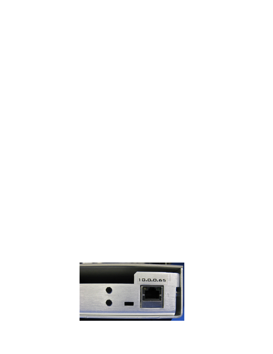
DDMI Interface Port
On the far right rear of the frame is an Ethernet port (
) for inter-
facing to the Digital Diagnostics Monitoring Interface (DDMI). This is an
Ethernet 10/100T compliant web-enabled port which allows remote moni-
toring of the VMCR and its installed VMC and MVMC modules.
To connect the CAT5 jack on the rear of the frame directly to a computer
(without the use of a router or hub), a CAT5 crossover cable is required. Set
the TCP/IP connection to the following:
•
The default IP address of the device is shown above the rear connector
(10.0.0.65 in the example in
).
•
The Subnet Mask is 255.255.0.0
•
The Gateway is 0.0.0.0 (none)
You may connect the device to a network router or hub on the same
network as your PC. Use a DOS Prompt window to ping the IP address of
the device to verify it is present on the network. Then use your web
browser (with Java 1.4.2 or later) to access this device by typing the IP
address of the device into the web browser address line.
Note
For more advanced Telnet access to the device, check with your system
administrator.
Diagnostic information and other functionality such as changing the IP
address for this device is discussed in the Frame Monitoring section of this
manual under
DDMI Web Page Status Monitoring on page 37
.
Figure 13. DDMI Ethernet Port