Grass Valley Fiber Media Converter User Manual
Page 24
24
Media Converters — Instruction Manual
Installation and Operation
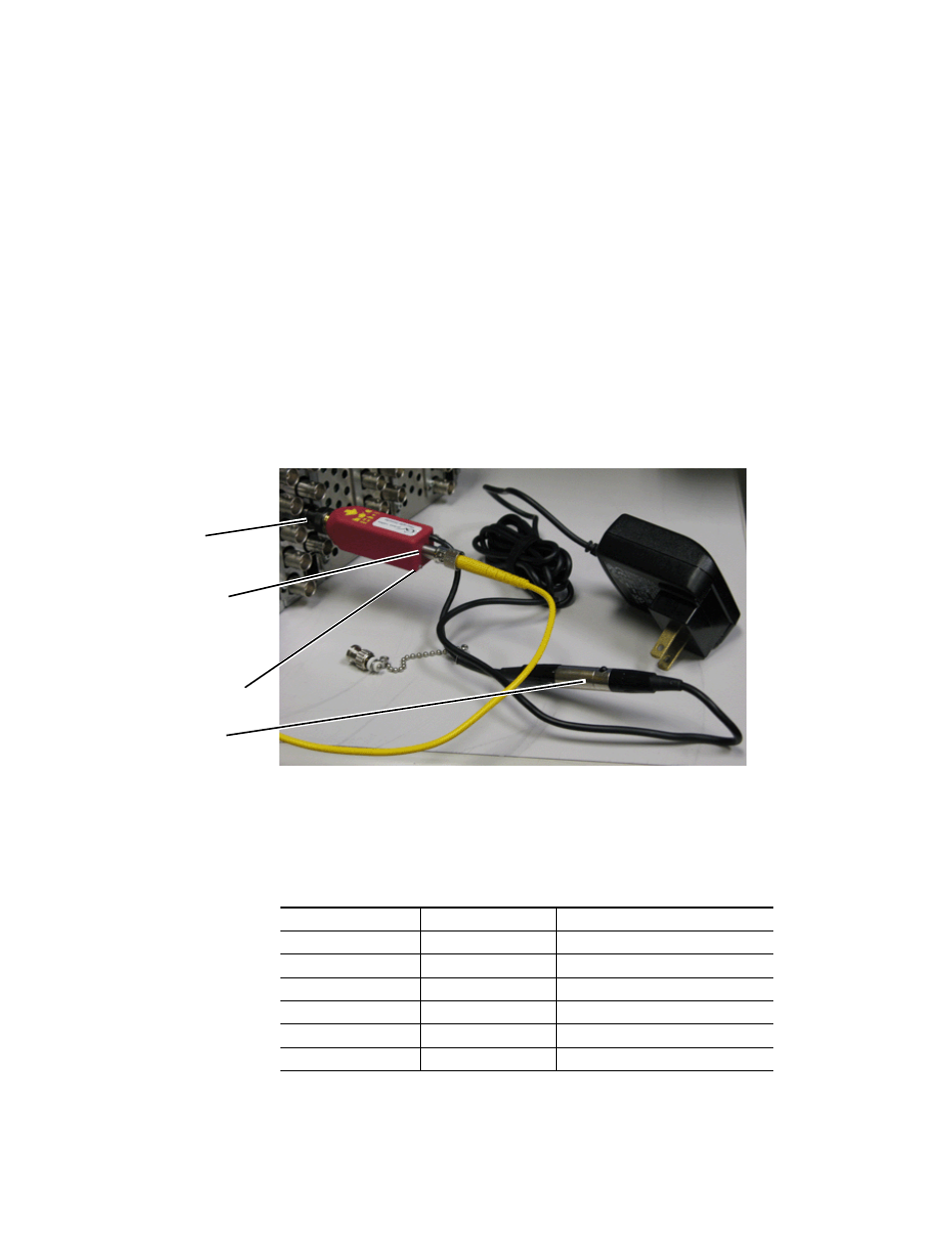
To connect a VMC or MVMC in a standalone application (
), do the
following:
1.
Connect the VMC or MVMC receiver or transmitter to the BNC of the
video device.
CAUTION These are Class A laser devices, use caution when handling laser signals.
2.
Remove the protective dust plug on the fiber optic connector and attach
the correct fiber optic link to the VMC or MVMC.
3.
Connect the Mini-XLR connection on the VMC or MVMC to the correct
type of wall plug power supply for your region of the world. Refer to
for the different models.
4.
Connect the wall plug to a power source (not shown).
Figure 10. VMC in Standalone Configuration
Both the VMC and the MVMC have mini-LEDs on the rear of the unit that
light to indicate the status of the signal (
The color and action of the LEDs are given in
Table 1. VMC and MVMC TX/RX Mini LED Status Conditions
Mini LED Status
TX (transmitter)
RX (receiver)
Green
Normal operation
Normal operation
Red
Transmit fault
Optical input signal out of range
Orange
N/A
Re-clocker not locked (VMC only)
Blinking Green
No cable connected
LOS (no optical input signal)
Blinking Red
DDMI Alarm
1
1
For DDMI (Digital Diagnostics Monitoring Interface) information, refer to
.
DDMI Alarm
1
Blinking Orange
DDMI Warning
DDMI Warning
BNC connection to
video equipment.
Fiber optic connection
to correct fiber type
Mini-XLR to Mini-XLR
power connection.
(transmit or receive).
Status indicator mini LED