Functional description, Input and ancillary data processing, Active picture processing – Grass Valley 8990ARC v.3.0 User Manual
Page 50
50
8990ARC Instruction Manual
Functional Description
Functional Description
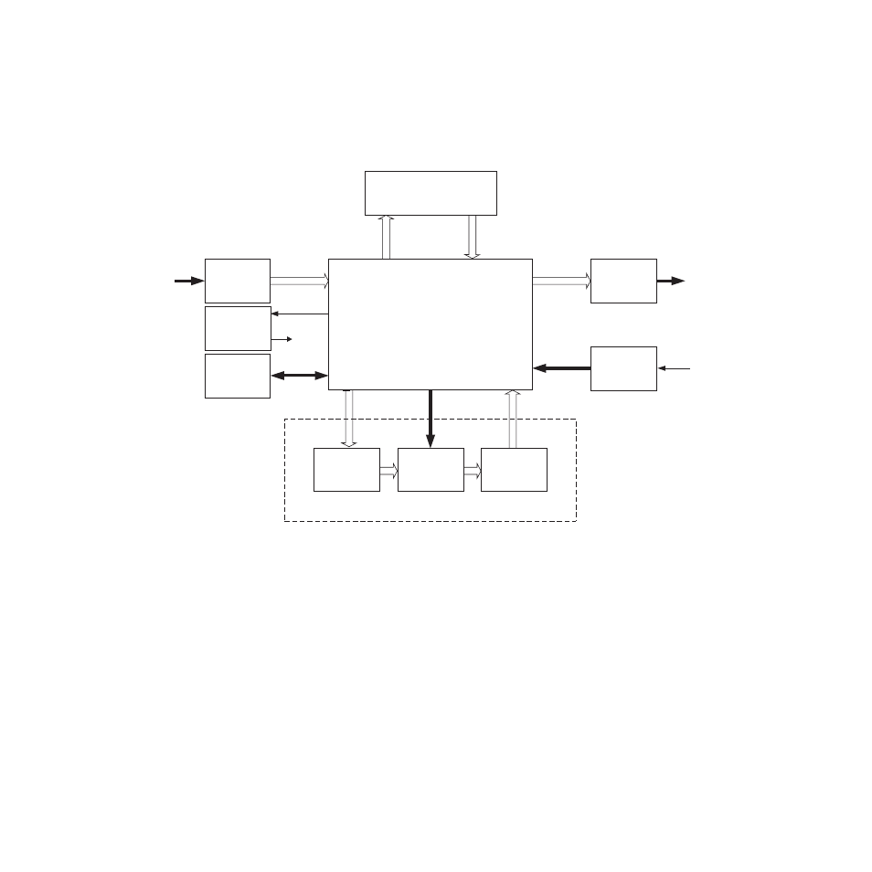
Refer to the block diagram in
while reading the following func-
tional description.
Figure 21. 8990ARC Block Diagram
Input and Ancillary Data Processing
The input signal is deserialized and enters the control Field Programmable
Gate Array (FPGA). Sync is detected and is used to H-lock the system 27
MHz clock. All horizontal and vertical interval data is routed through the
ancillary date (ANC) bypass FIFO to delay match the re-sized active
picture data and is multiplexed back, with the re-sized data, to the parallel
data output. This output is serialized and output through 4 buffers and
connectors.
Active Picture Processing
The active picture portion is routed through the H and/or V re-sizing
portion shown. Depending on the mode and input format selected, H and
V will be scaled up or down. The maximum delay for this processing is
270 Mb input
270 Mb
Output
ANC Bypass
H & V re-size processing
Processor
and
Power
27 MHz clock
and PLL
27MHz
input h--lock
Processor I/F and Control FPGA
Coefficient loading
and control
GPI Input A/D
Input Y & C
FIFOs
Output Y & C
FIFOs
Horiz & Vert
Polyphase
Filter
8036_01r1