Service – Grass Valley 8990ARC v.3.0 User Manual
Page 49
8990ARC Instruction Manual
49
Service
Service
The 8990ARC Digital to Analog Converter modules make extensive use of
surface-mount technology and programmed parts to achieve compact size
and adherence to demanding technical specifications. Circuit modules
should not be serviced in the field unless otherwise directed by Customer
Service.
If your module is not operating correctly, proceed as follows:
•
Check frame and module power and signal present LEDs.
•
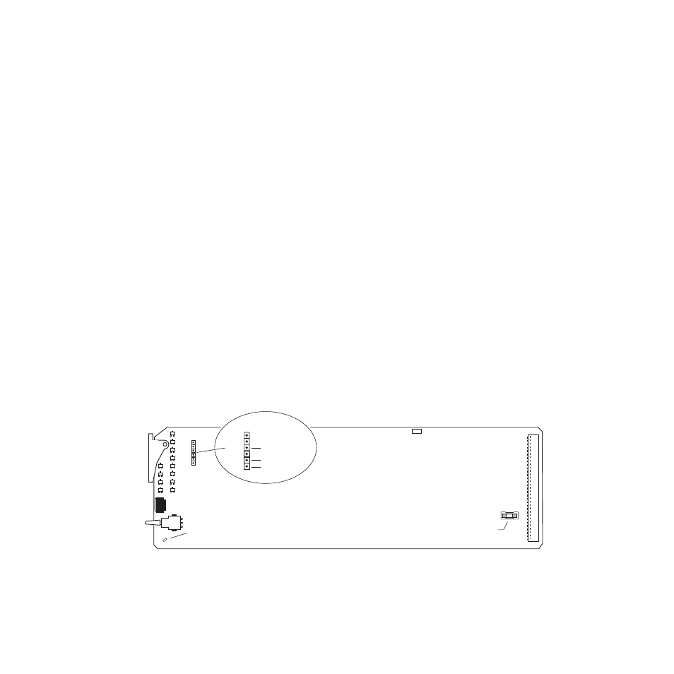
Verify power at the voltage testpoints (see
) and check Fuse F1
if no voltage is detected.
•
Check for presence and quality of input signals.
•
Verify that source equipment is operating correctly.
•
Check cable connections.
•
Check output connections for correct I/O mapping (correct input con-
nector is used for the corresponding channel output).
for the location of PWR LED and
for proper LED indications.
If the module is still not operating correctly, replace it with a known good
spare and return the faulty module to a designated Grass Valley repair
depot. Call your Grass Valley representative for depot location.
at the front of this document for the Grass
Valley Customer Service Information number.
Figure 20. Fuse and Voltage Testpoint Locations
GRASS VALLEY GROUP
8 9 9 0 A R C A S P E C T R A T I O C O N V E R T E R
6 7 1 - 5 2 4 6 -
Fuse: 2A,125V
F1
JP1
pin 3, +3 V
pin 5, -5 V
pin 6, +5 V
Voltage Testpoints
GND
8036_08r1