Functional description, Video input – Grass Valley 8981FS User Manual
Page 35
8981FS Instruction Manual
29
Functional Description
Functional Description
while reading the following func-
tional description.
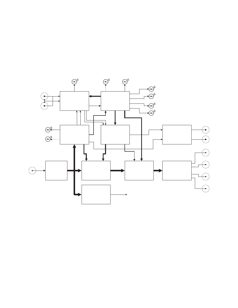
Figure 16. 8981FS Block Diagram
Video Input
The serial digital video input signal is deserialized to produce a 10-bit
digital signal at a 27 MHz word rate. This data feeds an EDH error detector,
the write inputs of the frame memory, and the write control timing logic.
The write control logic extracts timing information from the input data
stream and uses it to control the memory addressing so that any particular
point in the input video frame is always written to the same fixed address
in the frame memory. Data is read from the frame memory under control of
pixel and line counters in the read control and timing logic. The read
control timing and resulting frame memory output video timing is set by a
Deserializer
Write Control
Logic
Read Control
and Timing Logic
Memory
Genlock and Output
Timing Control
Output Signal
Processor and
EDH Inserter
Control
Microprocessor
Serializer and
Output Driver
Video
Input
Video
Outputs
Reference
Video Input
Reference
Present LED
2nd Function LED
Delay Mode LED
Freeze LED
Configure LED
Fault
LED
Communication
LED
525
625
Input
Present
LEDs
Audio Delay
Control Signal
Generator
Audio Delay
Control Outputs
EDH Error Detector
EDH Error Sense
Output to Microprocessor