Cabling, Input, Outputs – Grass Valley 8981FS User Manual
Page 12: Reference input, Delay control output
6
8981FS Instruction Manual
8981FS Digital Frame Synchronizer Module
Cabling
Note
At the back of this manual are overlay cards that can be placed over the rear
connector BNCs to identify the specific 8981FS connector functions.
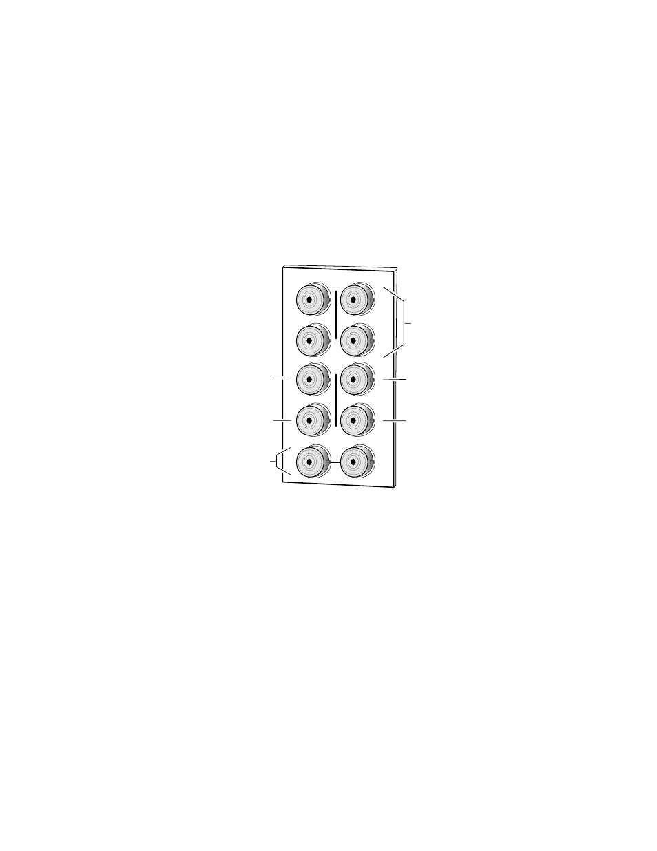
Input
Connect an input source to the input connector, J7 (see
8981FS input will accept either 8- or 10-bit Serial Digital Component video
per SMPTE 259M-C or EBU technical standard 3267.
Figure 3. 8981FS Input/Output Connectors
Outputs
The 8981FS has four serial digital video outputs—J1 through J4.
Reference Input
For operation as a Frame Synchronizer, a loop-through input is provided
for an analog color black 525- or 625-line signal. Acceptable sync level is 140
to 560 mV peak-to-peak. Terminate the unused connector into 75
Ω
if the
signal is not looped to other equipment. No reference input is required if
the module is used as a fixed Delay.
Delay Control Output
Two audio delay control outputs (J5 and J6) are provided for input to Grass
Valley Auto-tracking Delay DAs for audio synchronization. A BNC Tee
connector can be used if more than two audio delay modules are required.
J2
J4
J6
J8
J1
J9 J10
IN
Four Component
Serial Digital Video
Outputs
X
O
U
T
J3
J5
J7
J2
J4
J6
J8
0719_02
Loopthrough
Reference Input
Component Serial
Digital Video Input
GPI
Delay Control
Signal Output
Delay Control
Signal Output