Gpi freeze trigger circuits, Gpi circuit design, Eeze mode (see gpi freeze trigger circuits – Grass Valley 8981FS User Manual
Page 31: For mor
8981FS Instruction Manual
25
GPI Freeze Trigger Circuits
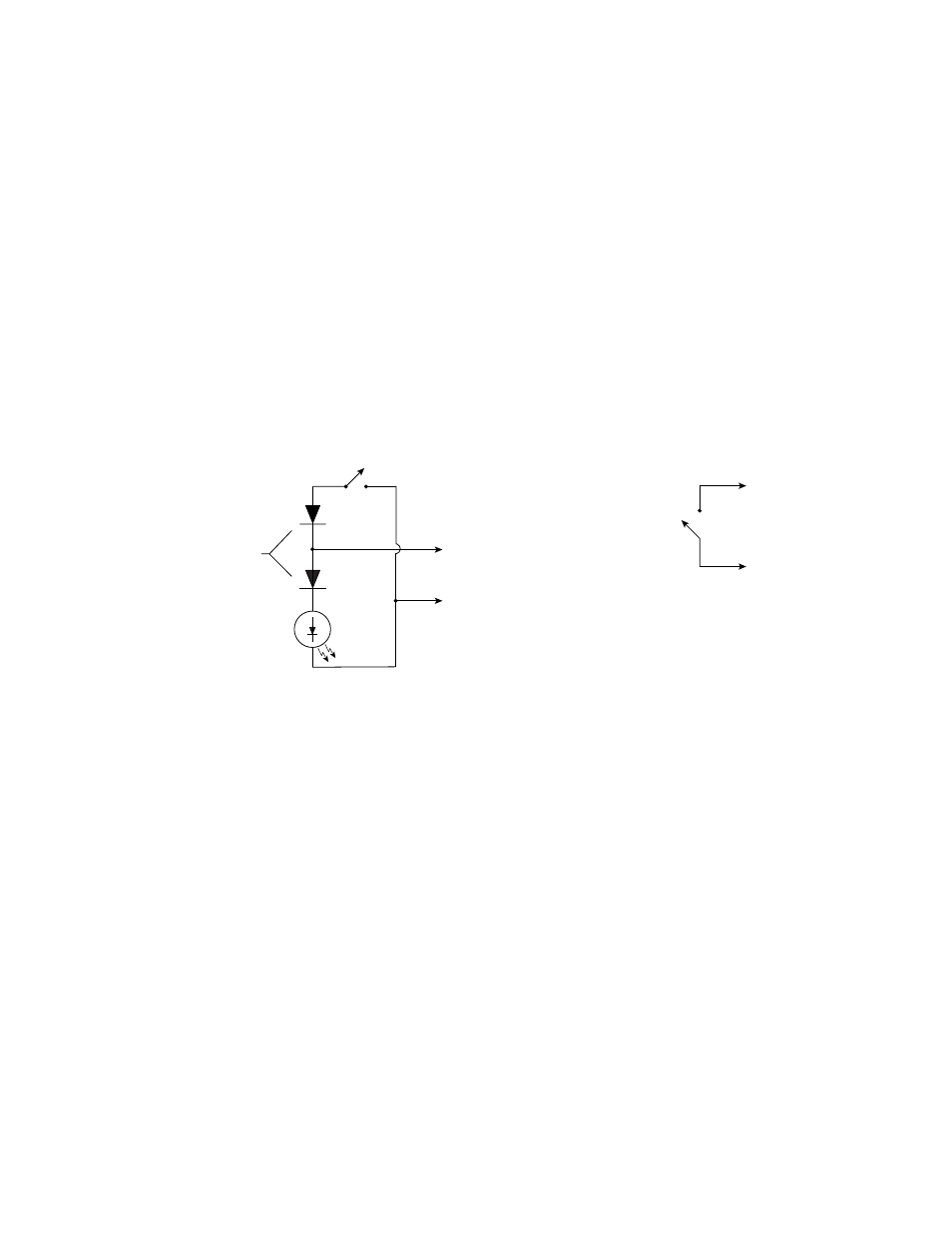
GPI Freeze Trigger Circuits
provides two sample circuits, with and without remote indicator
LED, that can be used to manually trigger the Freeze output when the GPI
Remote Freeze function is enabled (see
). Refer to the
Configuration table to select whether the 8981FS alternates between
freeze/no freeze or stays in freeze mode only while the remote freeze
switch is closed.
If a Remote Freeze indicator is not required, no diodes are needed. Simply
connect the freeze control switch to ground the center pin.
Figure 15. Typical User-supplied Circuits for GPI Freeze Triggering
GPI Circuit Design
The GPI BNC connector is both a manual freeze mode control input and an
output to drive a remote freeze indicator. To provide both functions inde-
pendently, two diodes are required at the remote control panel as well as a
switch and indicator LED. This line pulls up for approximately 15 ms to
light the indicator if freeze mode is active, then down below ground for 1
ms to test for the presence of a catch diode. The catch diode will function to
limit how far negative the line can go only when a switch closure connects
the diode to ground. The module detects this change in how far below
ground this control input goes and uses it to control the freeze mode. When
in freeze mode, this cycle continuously repeats so the indicator is driven
with a 94% duty cycle. When not in freeze mode, the line does not pull high
(the indicator is not illuminated) but the line still pulls negative to test for
the catch diode. The module supplies limited current both when pulling up
and down on this line. No damage will be done if the line is tied to ground.
If no remote freeze indicator is needed the diodes can be eliminated and
only a contact closure to ground is required to initiate freeze mode.
With Indicator LED
Without Indicator LED
Freeze
Control
Switch
GPI Connector
BNC Center Pin
Shield/Ground
Freeze
Indicator
LED
Any Standard
Signal Diodes
Freeze
Control
Switch
GPI Connector
BNC Center Pin
Coaxial cable is not required
for this connection.
Shield/Ground
Note:
0719-07