Grass Valley 8981FS User Manual
Page 14
8
8981FS Instruction Manual
8981FS Digital Frame Synchronizer Module
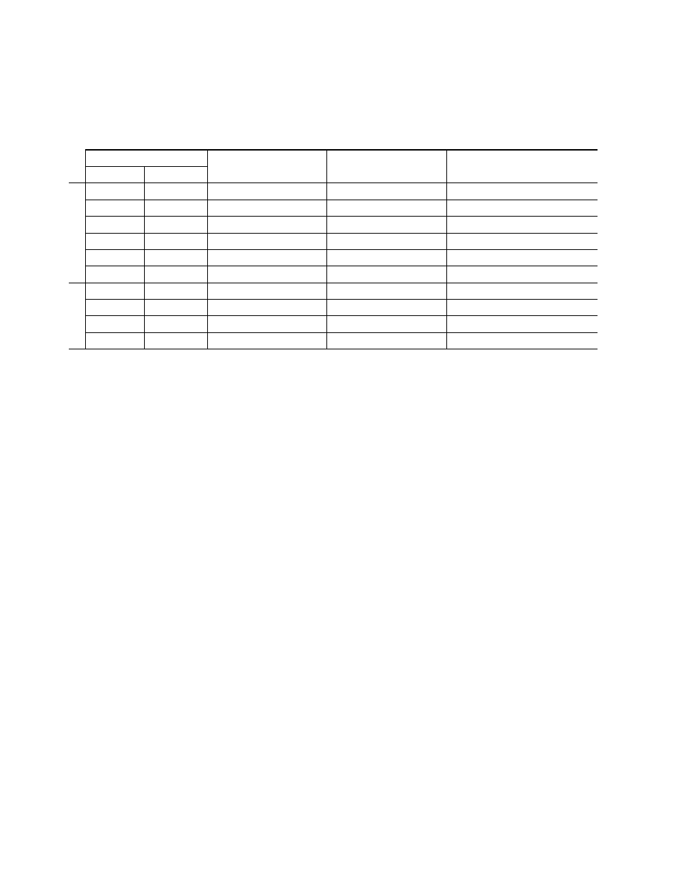
describes the output that will be seen under the various possible
input operating modes and conditions.
Table 2. Possible Operating Conditions
Mode Settings
Video Input Condition
Reference Input Condition
Resulting Output
Auto-freeze
Forced Black
Frame Sync
N.A.
1
1
N.A. = Not Affected—output signal is not affected by this mode setting or input under these signal conditions.
N.A.
1
Video input present
Valid reference input present
Normal output
Off
Off
No video input present
Valid reference input present
Passes any input signal
On
Off
No Video input present
Valid reference input present
Freeze of last good field
N.A.
1
On
No Video input present
Valid reference input present
Black output
N.A.
1
N.A.
1
Video input present
Reference input not present
Forced to fixed delay mode
N.A.
1
N.A.
1
Video input present
Wrong line standard Reference
Bad output signal
2
2
Unusable output signal if video input and reference are not the same line standard.
Delay
N.A.
1
N.A.
1
Video input present
N.A.
1
Normal output
Off
Off
No video input present
N.A.
1
Bad output signal
3
3
Output will contain EAV/SAV timing reference signals but they will be far from normal line frequency.
On
Off
No video input present
N.A.
1
Bad output signal
4
4
Output will be Freeze of last good field before input lost but will be far from normal line frequency.
N.A.
1
On
No video input present
N.A.
1
Bad output signal
5
5
Output will be black video but will be far from normal line frequency.