Onboard module configuration switches and leds, D module configuration – Grass Valley 8950ADC User Manual
Page 18
18
8950ADC Instruction Manual
Configuration
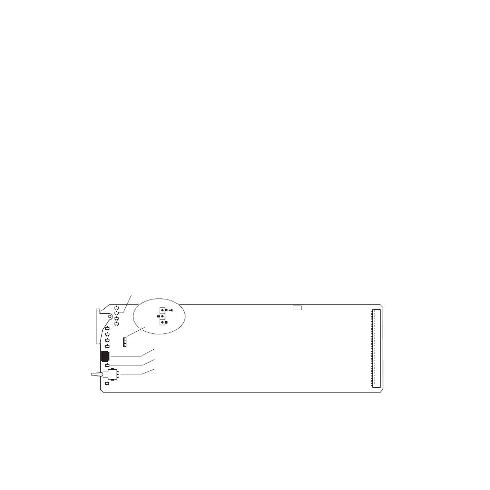
Onboard Module Configuration Switches and LEDs
The 8950ADC module can be configured locally using the rotary and
paddle switches shown in
. The CONF and 2ND func-
tion LEDs are configuration status indicators. These four components
perform the following:
•
Function (rotary) switch — This switch is used to access a desired func-
tion for configuration. The switch addresses two banks of functions;
each bank has 16 possible positions (0 through 9 and A through F). Not
all positions are used (see
). The alternate bank of
functions is accessed each time the Function Switch makes a complete
revolution past zero: While in Bank 1, a complete revolution past zero
accesses Bank 2; while in Bank 2, a complete revolution past zero
accesses Bank 1. The 2ND LED indicates which bank is currently being
accessed.
Note
The Function switch should be kept in the position for the selected mode (1
through 7) or in position 0 when not in use to avoid any inadvertent change
in configuration. 0 is an inactive position.
•
SW2 (paddle) switch — Actuates or selects the desired setting for the
selected function when the switch is held momentarily in either the up
or down position.
•
2ND LED — When on, indicates that user is accessing the second bank
of configuration parameters.
•
CONF (configuring) LED — When on, indicates the module is initial-
izing or processing configuration information.
Figure 5. Module Configuration Switches and LEDs
GRASS VALLEY GROUP
8 9 5 0 A D C
6 7 1 - 4 7 9 9 -
J P 2
J P 2
L O C A L
R E M O T E
FUNCTION – rotary switch
SW2 – paddle switch
2nd – second function LED
CONF – configuration LED
0603_05r1