Power up, Operation indicator leds – Grass Valley 8950ADC User Manual
Page 11
8950ADC Instruction Manual
11
Power Up
Power Up
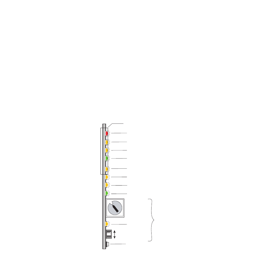
The front LED indicators and configuration switches are illustrated in
. On power-up the green PWR LED should light and the yellow
CONF LED should illuminate for the duration of module initialization.
Operation Indicator LEDs
With factory default configuration and a valid input signal connected, the
green PWR LED, and one of the yellow signal standard LEDs (525 or 625)
should illuminate (refer to
to see the possible operating
indicator combinations).
Video input presence is indicated by an illuminated VID PRES LED and the
appropriate 525 or 625 LED. The 525 or 625 LED will illuminate to indicate
detection of a 525-line or 625-line input signal. The VID PRES LED indi-
cates the presence of valid composite sync on the Y/G channel or reference
input.
Figure 4. LEDs and Configuration Switches
16-position
Rotary switch
Momentary toggle switch
525 – Yellow LED on indicates 525 mode input
PWR – Green LED on indicates power OK
FAULT – Red LED is off during normal operation
Ejector Tab
COMM (Yellow)
CONF (Yellow)
MAN MODE – Yellow LED on indicates manual input selection
625 – Yellow LED on indicates 625 mode input
VID PRES – Green LED on indicates a valid video input signal is present
Module Configuration Switches and LED
GND
2nd Function
(Yellow)
0603_06r1
0
1
2
3 4
5 6 7
8
9
A
B
CD
E
F