Tsl protocol version 3.1 – Grass Valley 8949SVM-LOC User Manual
Page 38
38
8949SVM-LOC/-UMD—Instruction Manual
TSL Protocol Version 3.1
TSL Protocol Version 3.1
The following section describes TSL protocol version 3.1 in
and
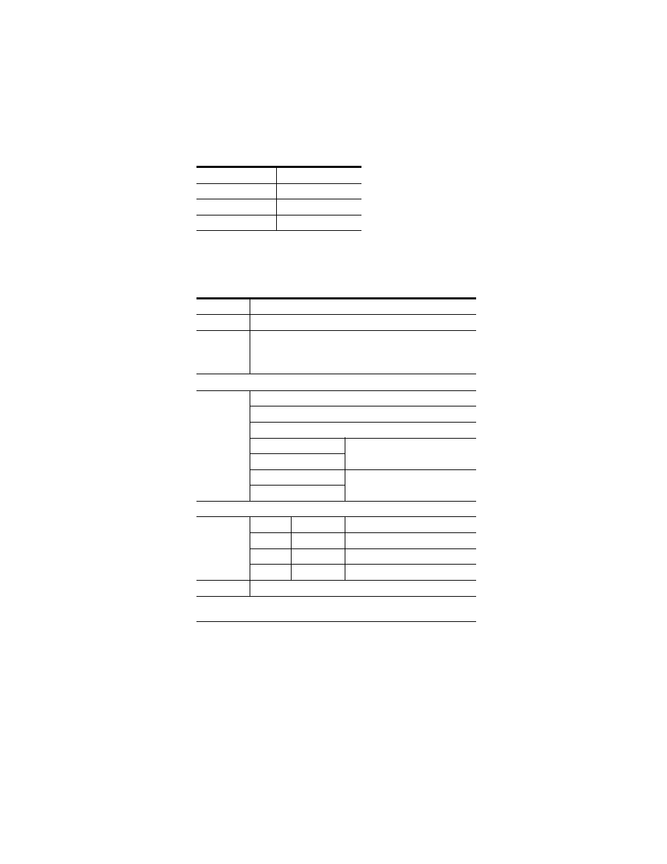
Table 4. Version 3.1 Byte Offsets and Functions
Byte Offset
Function
0
Unit ID
1
Tally Control
2-17
UMD Text
Table 5. 3.1 Protocol Description
Unit ID
Unit Level Addressing for Multicast Data
(Bit 7)
Must be 1
(Bit 6..0)
Unit addresses are in range 0...126. The value of 127 is taken to
address all units (to which the packets are delivered). Unit address
is controlled by the Multicast ID set through the paddle switch con-
trols.
Tally Control
(Bit 7)
Must be 0
(Bit 6)
Must be 0
(Bit 5..4)
Not used
(Bit 3)
Tally 4
Selecting both Tally 3 and Tally 4 is
undefined behavior
(Bit 2)
Tally 3
(Bit 1)
Tally 2
Selecting both Tally 1 and Tally 2 is
undefined behavior
(Bit 0)
Tally 1
Tallies are mapped as follows:
Tally 4
Right Green
0: Off; 1: On
Tally 3
Right Red
0: Off; 1: On
Tally 2
Left Green
0: Off; 1: On
Tally 1
Left Red
0: Off; 1: On
UMD Text
16 characters
UMD text characters includes the standard ASCII character set along with an
Extended Character set described in