Cabling, Video hd/sd input, Video hd/sd outputs – Grass Valley 8949SVM-LOC User Manual
Page 14: Dvi-i connector
14
8949SVM-LOC/-UMD—Instruction Manual
Cabling
Cabling
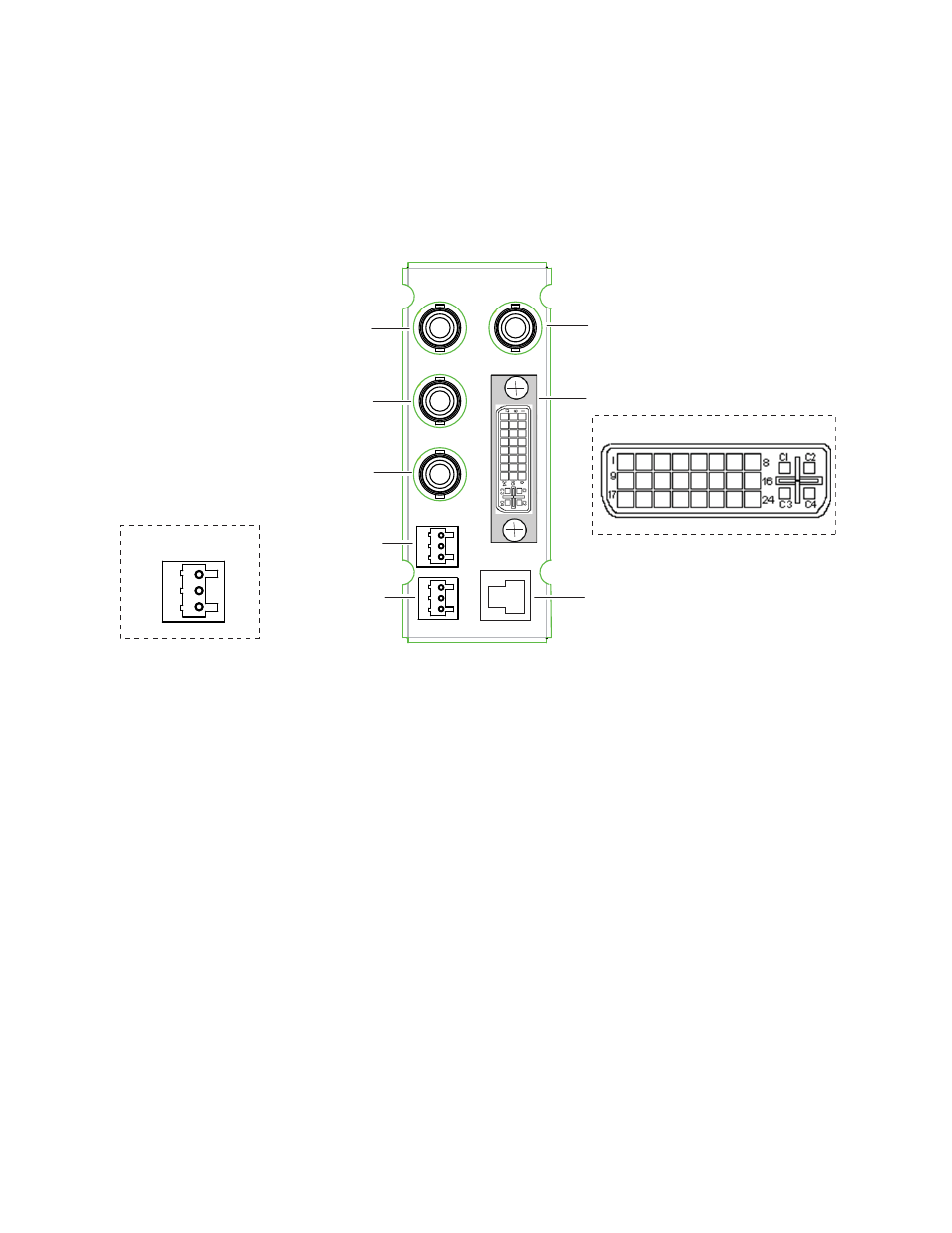
Cabling to either model version of the 8949SVM module is done on the con-
nectors on the 8900AVM-R rear module as shown in
and described
below.
Figure 3. 8900AVM -R Rear Cabling
Video HD/SD Input
The module has one input BNC that accepts an HD or SD SDI video signal
at BNC J1. The input is auto-sensing. Video standards accepted by the
module are listed in
Video HD/SD Outputs
There are two looping HD/SD SDI video outputs on BNCs J3 and J5.
Outputs follow the video input.
DVI-I Connector
A DVI-I connector at J4 outputs the scaled video input to the external mon-
itor. The DVI-I connector is detailed on the right of
. This connector
accepts a DVI-I cable or cable adapter if using a VGA monitor. Supported
output resolutions are listed in
8900AVM-R
Balanced Analog
Audio Out (Left)
Balanced Analog
Audio Out (Right)
HD/SD
SDI In
DVI-I Connector
Audio Pinout Detail
DVI-I Connector Detail
J1
J3
J4
J5
G
+
-
G
+
-
J6
J7
J8
J2
8613_02
HD/SD
SDI Out
HD/SD
SDI Out
(Not used in
this model)
Used in operation mode with
8949SVM-UMD and in upgrade
mode on 8949SVM-LOC and
8949SVM-UMD models.
G
+
-