Grass Valley 8947RDA-D User Manual
Page 25
8947RDA-D/-FR — Instruction Manual
25
Power Up
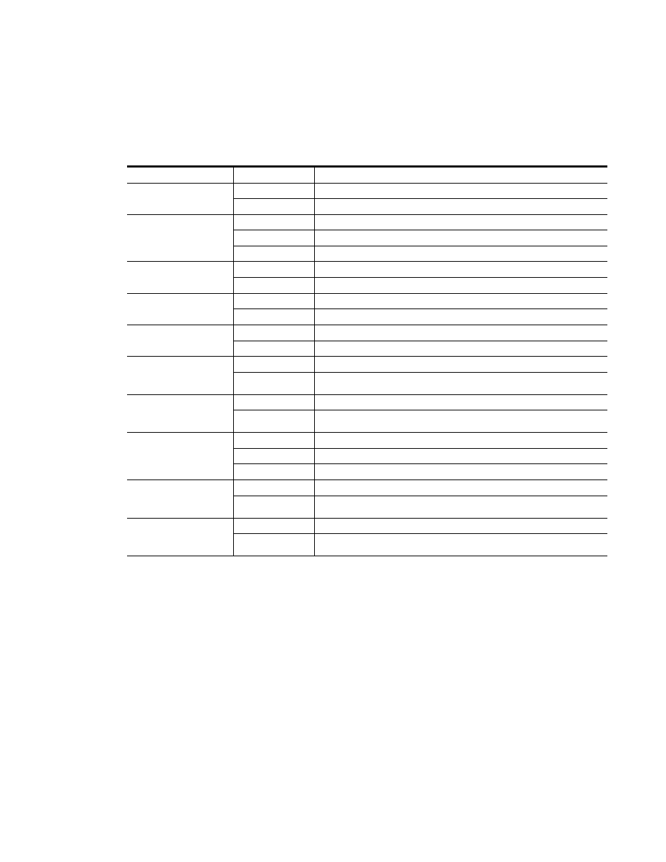
A red FAULT LED indicates an error situation and, when noted with the
other indicator LEDs, can indicate a specific problem area.
describes
signal output and LED indications for the various input/reference combi-
nations.
Table 6. LED Indicators
LED
Indication
Condition
FAULT
(red)
Off Normal
operation
On continuously
Module has detected internal fault
COMM
(yellow)
Off
No activity on frame communication bus
Long flash
Location Command received by the module from a remote control system
Short flash
Activity present on the frame communication bus
CONFIG
(yellow)
Off
Module is in normal operating mode
On continuously
Module is initializing, changing operating modes or updating firmware
PWR
(green)
Off
No power to module or module’s DC/DC converter failed
On continuously
Normal operation, module is powered
OPT MODULE PRESENT
(yellow)
Off
Fiber optic SFP device not installed
On
Fiber optic SFP device installed
Channel 1 and 2
PRES OPT IN
(green)
Off
Indicates no signal carrier present on the optical connector
On
Indicates signal carrier present on the optical connector
Channel 1 and 2
PRES COAX IN
(green)
Off
No presence of signal on BNC J9 (Channel 1) or J10 (Channel 2) connector
On continuously
Presence of signal on NC J9 (Channel 1) or J10 (Channel 2) connector
Channel 1 and 2
SD/HD/ASI
(yellow)
Slow Flashing
Indicates SD SDI signal present
Fast Flashing
Indicates HD SDI signal present
On continuously
Indicates ASI signal present
Channel 1 and 2
LOCK
(yellow)
Off
Indicates reclocker is unlocked
On continuously
Indicates reclocker is locked
Channel 1 and 2
BYPASS
(yellow)
Off
Indicates reclocker is not bypassed
On continuously
Indicates reclocker is bypassed