Power up, For the – Grass Valley 8900NET v.4.4.0 User Manual
Page 20
20
8900NET (Net Card) — Instruction Manual
Power Up
Power Up
The various front LED indicators and configuration switches on the
8900NET module are illustrated in
. Upon power-up, all LEDs
should light for the duration of the initialization process. The frame is
powered up when either of the AC mains connections are made on the rear
of the frame (
for Gecko frame and
for GeckoFlex frame).
After initialization the Power LED will be on and the red Network Module
LED (labeled NM) should be off. All other LEDs report detected fault con-
ditions within the frame and the installed modules. If the NM LED does not
go off, the board needs servicing.
Note
When a media module is first plugged into an 8900 frame, the 8900NET
module may report a momentary fault. This will clear once the media module
has booted up.
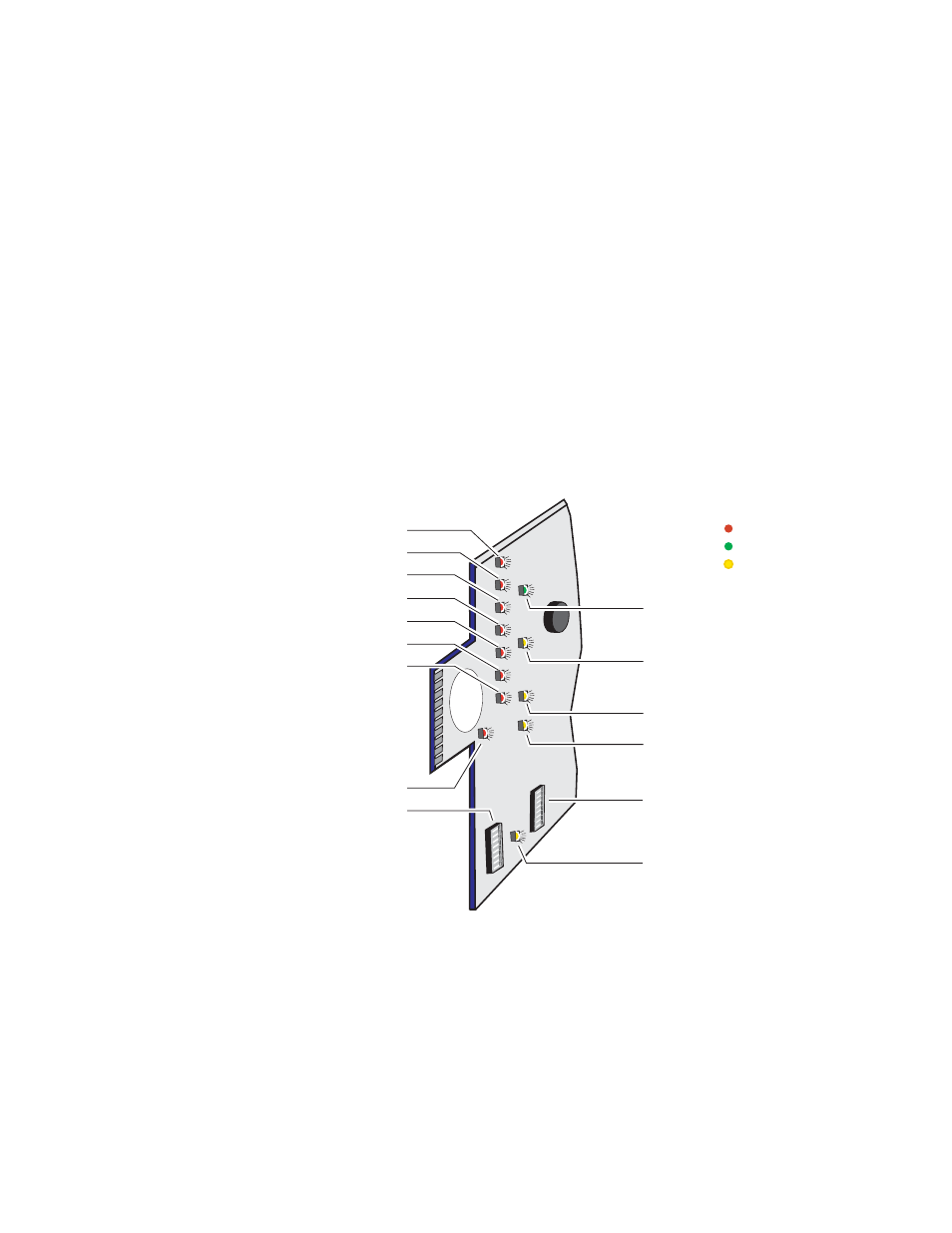
Figure 12. LEDs and Configuration Switches on the 8900NET Module
LEDs on the 8900NET module primarily indicate status items from the
frame and the modules in the frame. Some functions specific to the
8900NET module are also reported (PWR, ETHER, COMM). LED reporting
for each specific LED on the front of the 8900NET module can be disabled
if desired on the LED Reporting web page (
describes all the module’s LEDs and the conditions indi-
cated.
FAN (red)
MOD - Module Health Bus (red)
PS1 - Power Supply 1 (red)
PS2 - Power Supply 2 (red)
TEMP - Temperature (red)
S1
8
7
6
5
4
3
2
1
8
7
6
5
4
3
2
1
PWR - Power (green)
Red = Fault
Green = OK
Yellow = Active
LED Color Key
NM - Network Interface Module (red)
FB - Frame Bus (red)
COMM - Communication (yellow)
ETHER - Ethernet communiction
(yellow)
REM OVR - Remote Override
(yellow)
FAULT - Frame Fault (red)
INHIB - Module Health Inhibited
(yellow)
Configuration DIP switch S1
0612 -06
r1
Configuration DIP switch S2